SHIKISAI GeoTIFF-Level1B | Atmosphere | Cryosphere | Land | Ocean

Level-1B Products

Level 1B products are provided in HDF5 files for each of Visible-Near Infrared (non-polarization)/VNR-NP, Visible-Near Infrared (polarization)/VNR-PL, and Short Wavelength Infrared (Thermal Infrared)/IRS (SWI+TIR).
This section describes how to convert HDF5 Level-1B products obtained from G-Portal into map projection images and output them as GeoTIFF files.

The following methods are available to use SHIKISAI Level 1B data in GeoTIFF files.

* How to convert standard data obtained from G-Portal

  • -CUI: SGLI Map projection & GeoTIFF conversion tool (The link to the download site is provided from "Tools used" below.)
  • -GUI: Earth Observation Data Conversion Tool(Click on the tool name to go to the download page)

* How to obtain GeoTIFF from G-Portal processing requests

Tools

This section provides examples of GeoTIFF conversions using the following tools.
Click on the tool name to go to the download page.

Target product Tool name  

Level-1B(L1B) VNR/IRS/POL

SGLI Map projection & GeoTIFF conversion tool
Link to the "Tools & Documents" page in G-Portal.
Platforms: Windows, Linux

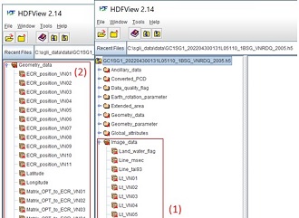
Level-1B(L1B) VNR/IRS/POL
For confirmation of SD array (data set name)
QGIS(Quantum GIS)/gdal Link to an external site.
Platforms: Windows, Linux

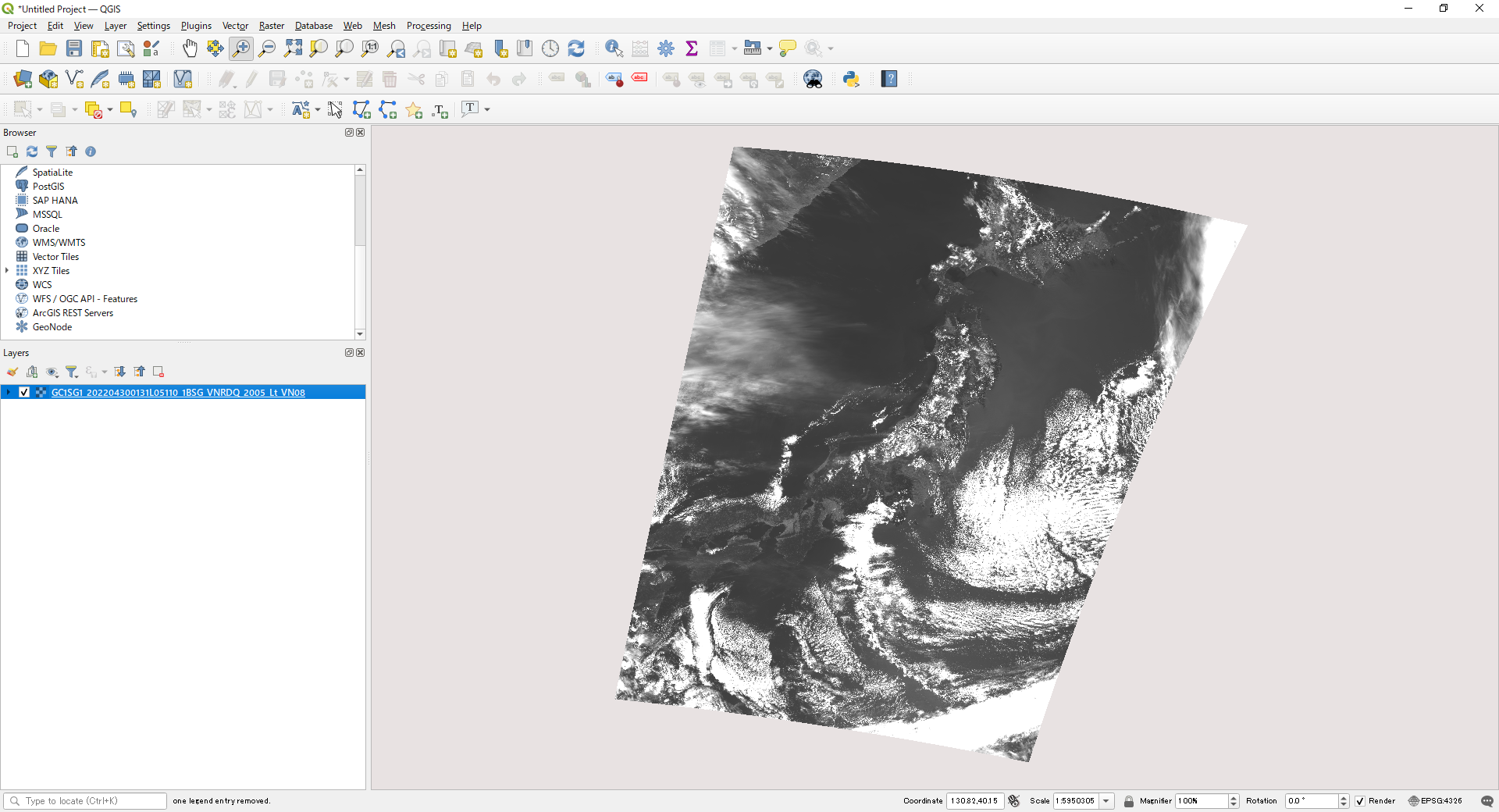
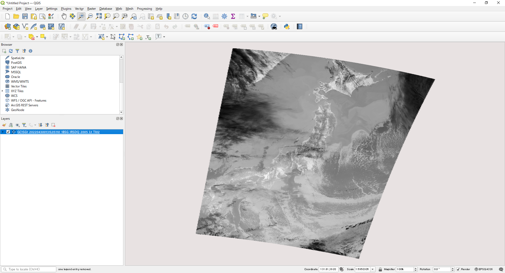
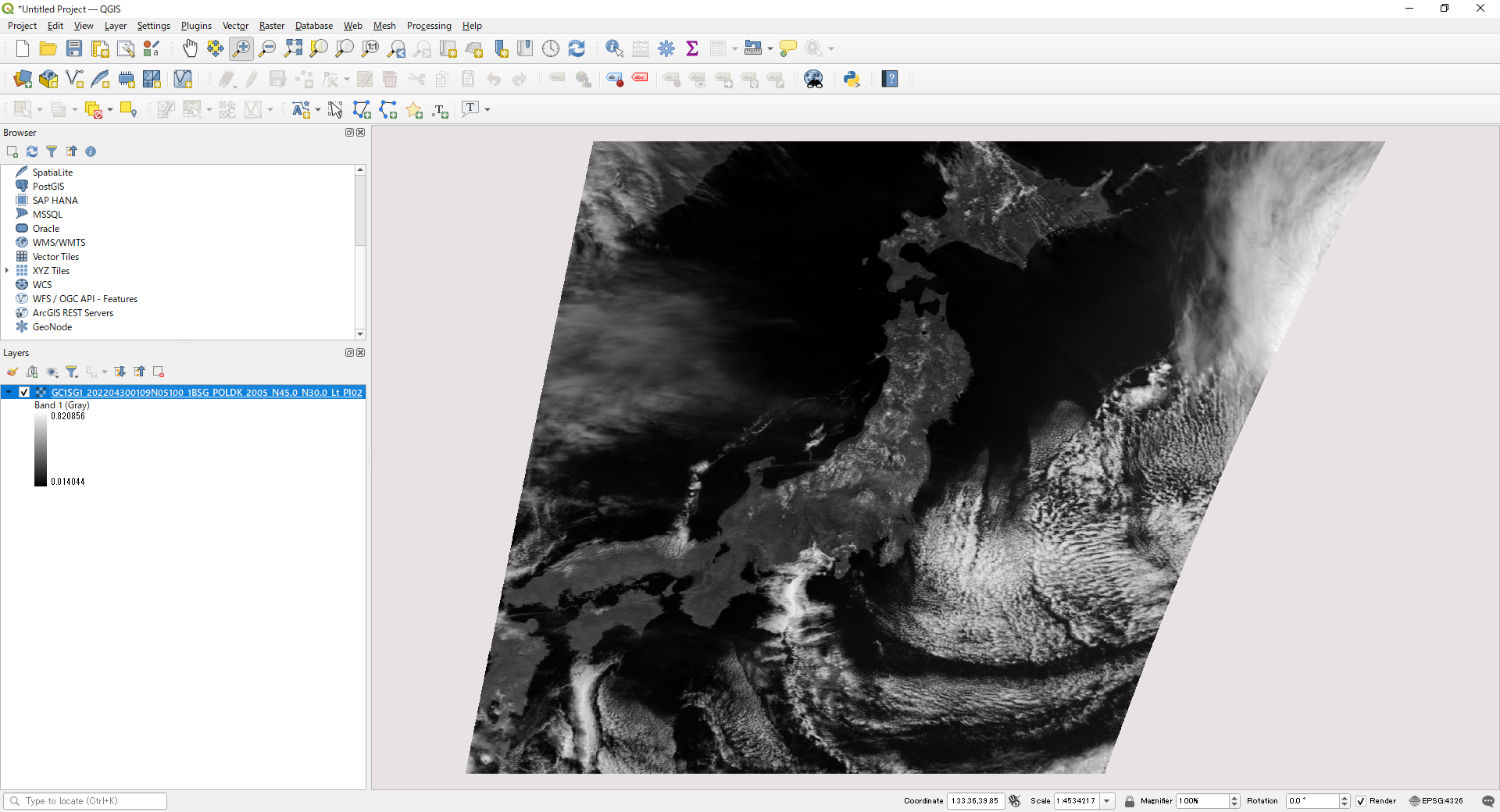
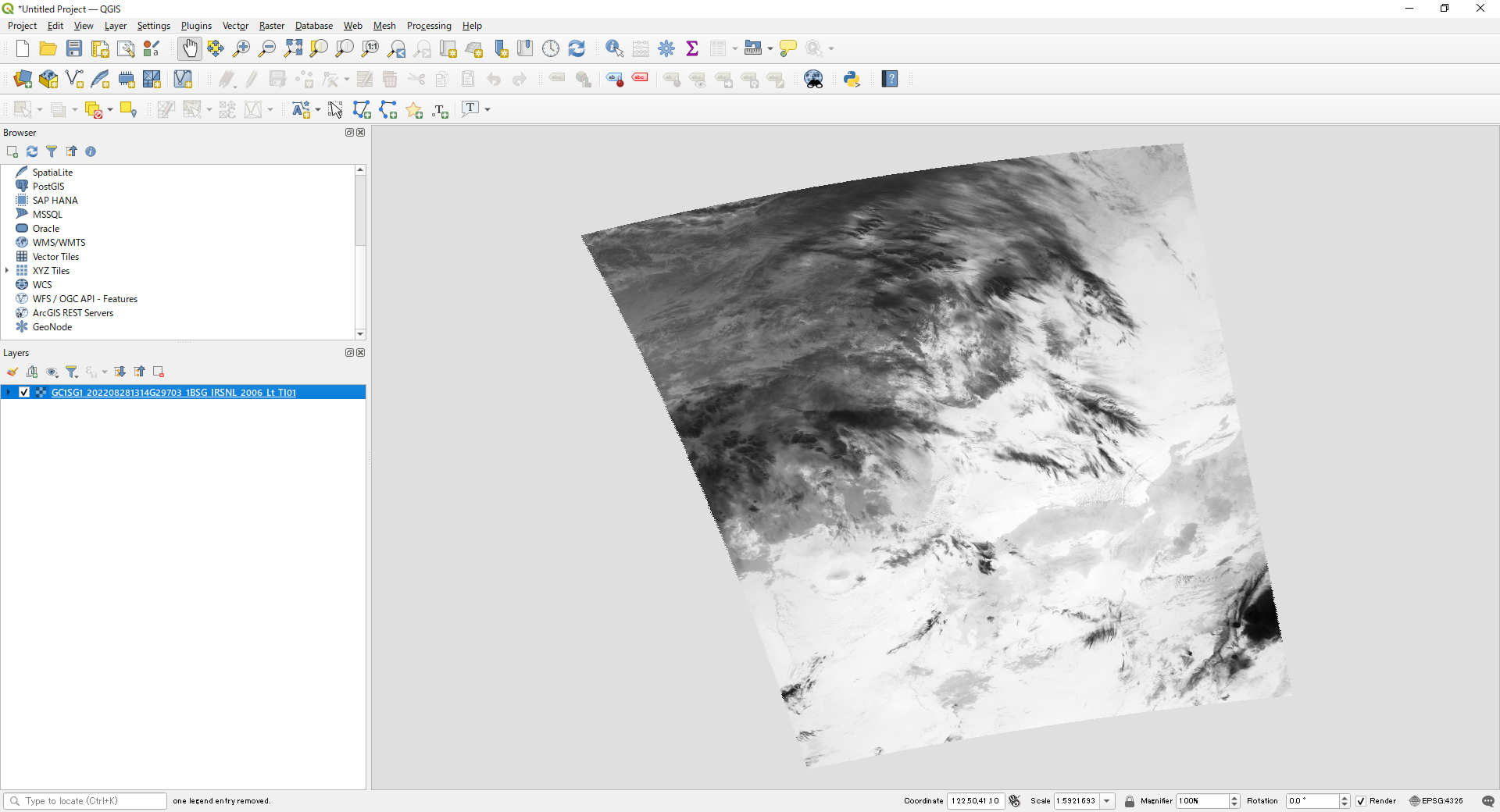
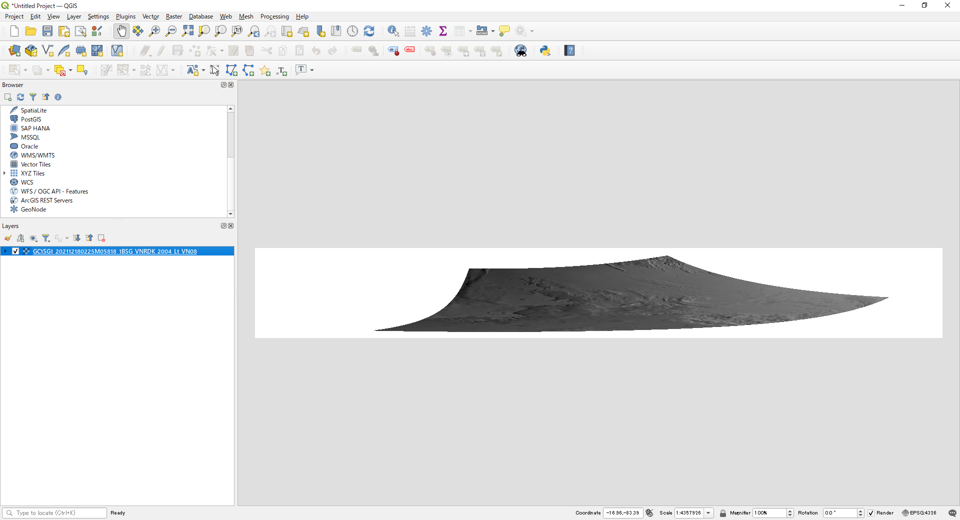
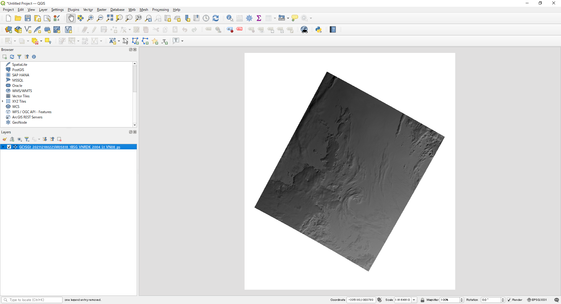
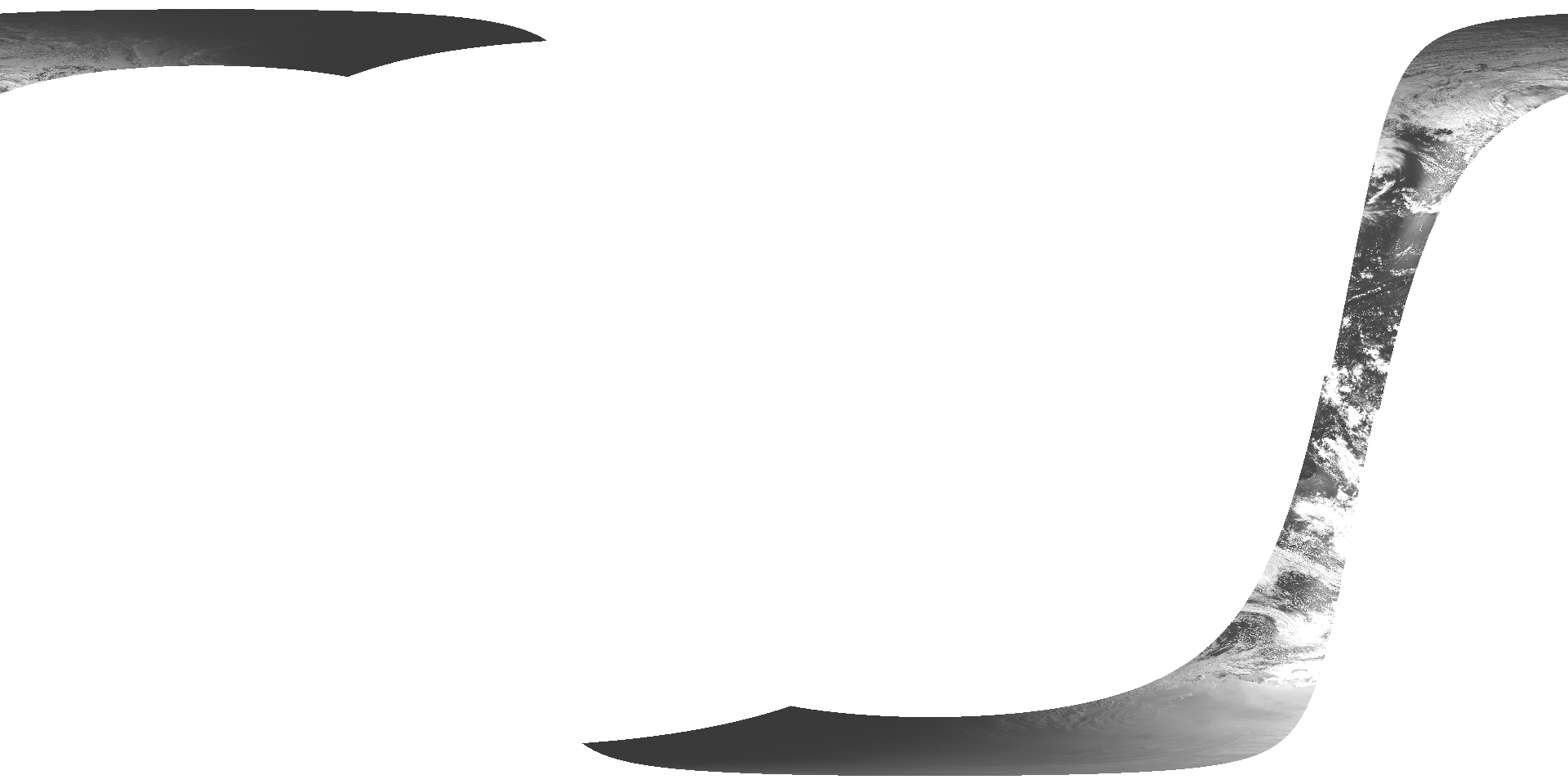
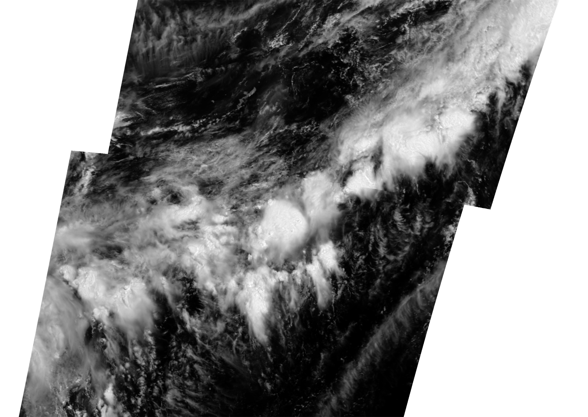
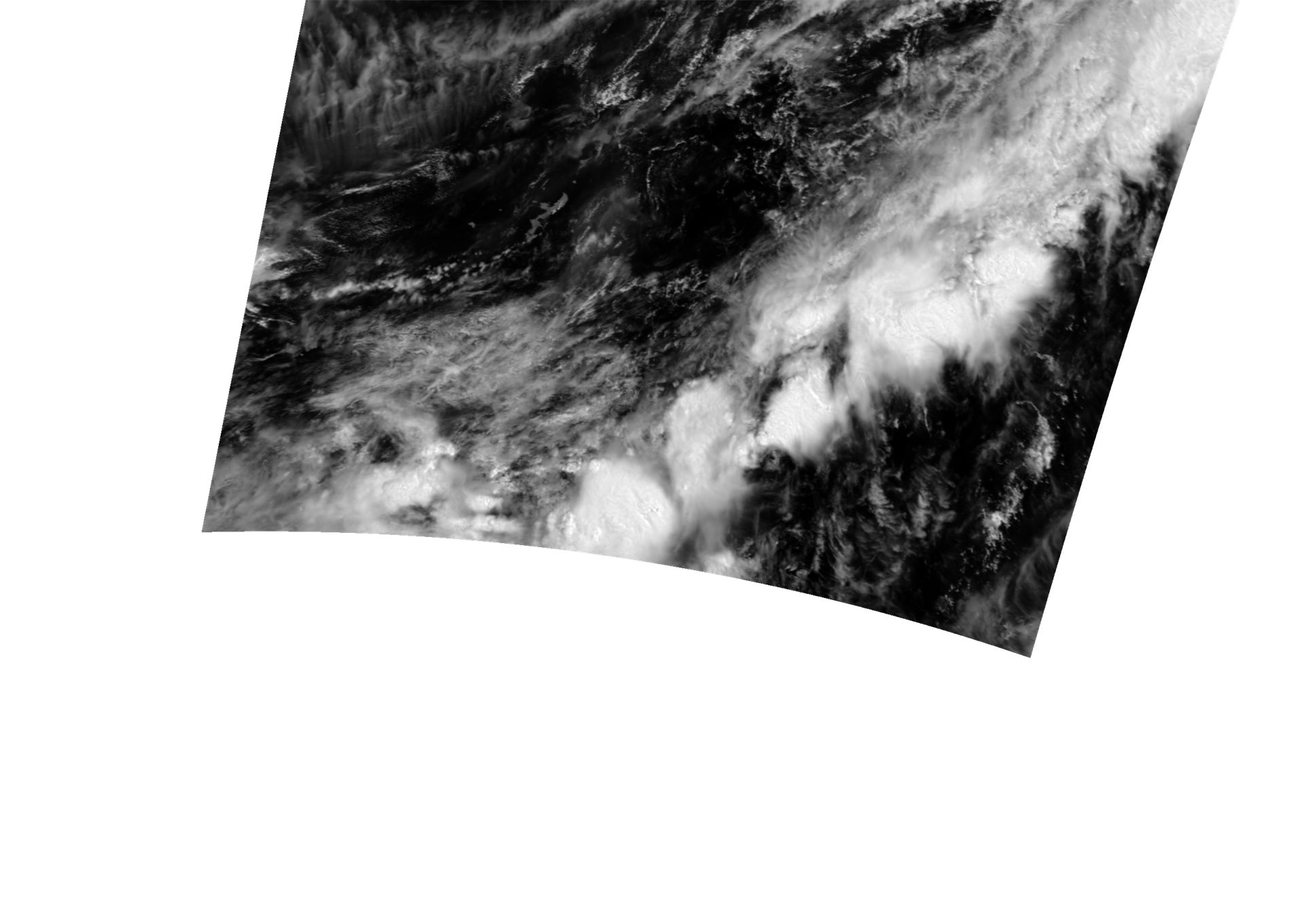
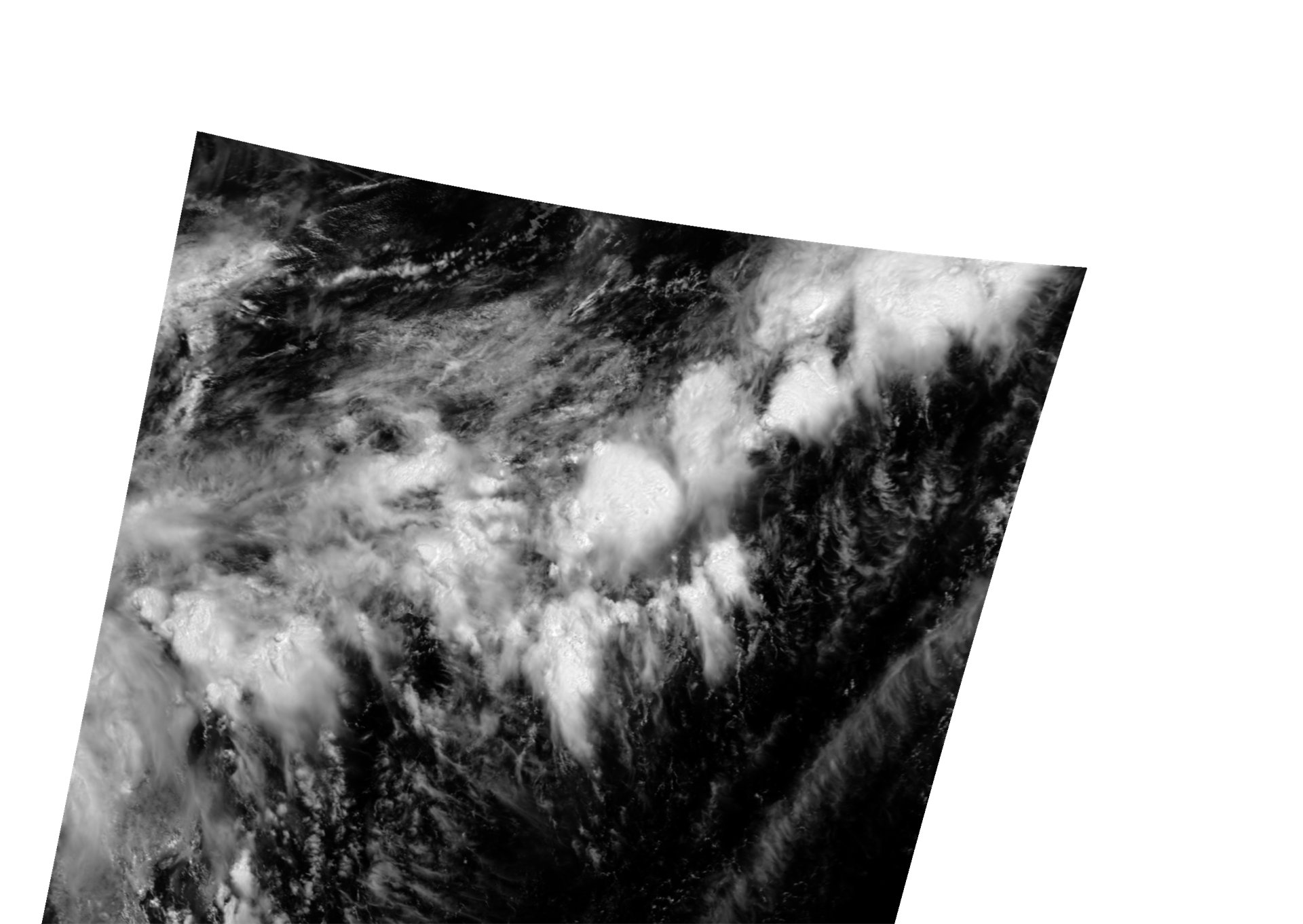
Example of GeoTIFF output from the "SGLI Map projection & GeoTIFF conversion tool" and displayed in QGIS.

Descending (D) / Daytime image (VNR, POL, IRS)

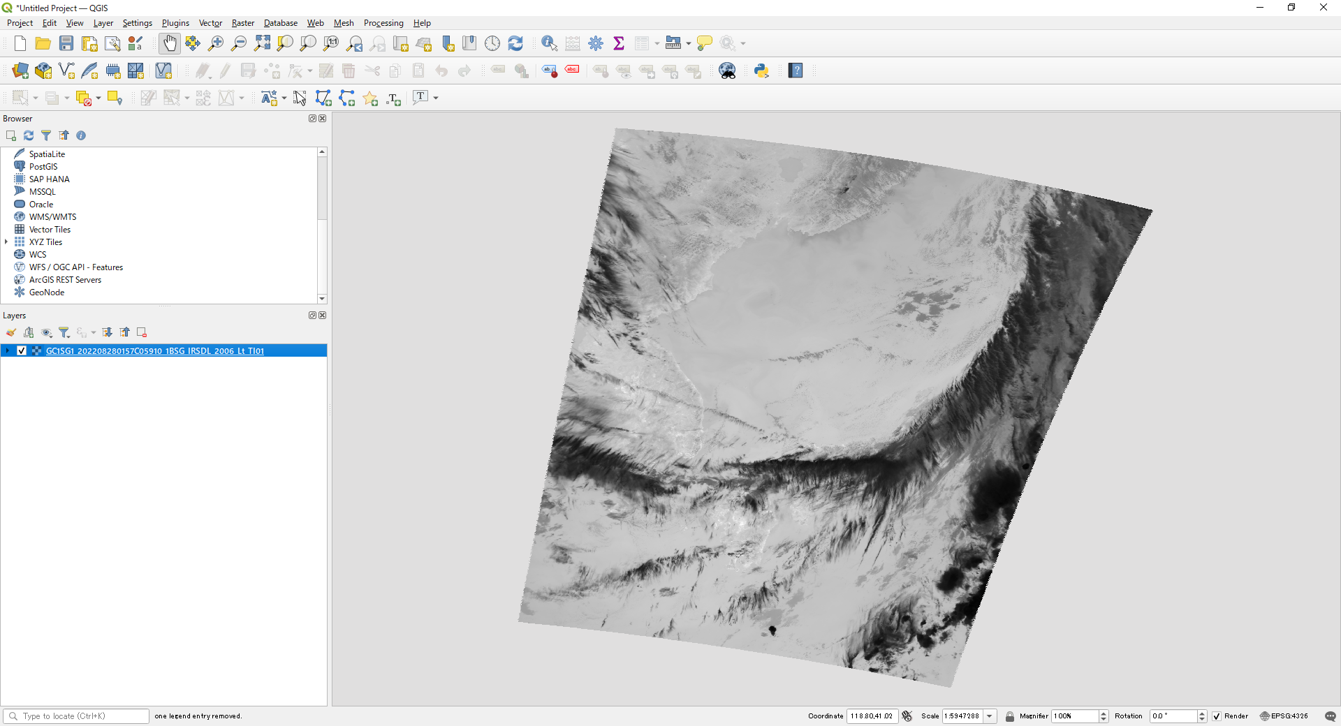
Ascending (A) / Nighttime image (IRS)

180deg crossing (default: Geodetic Lat/Long)

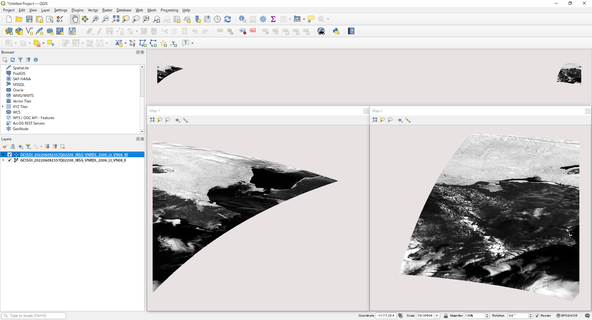
180deg crossing (Polar-Stereo (PS))

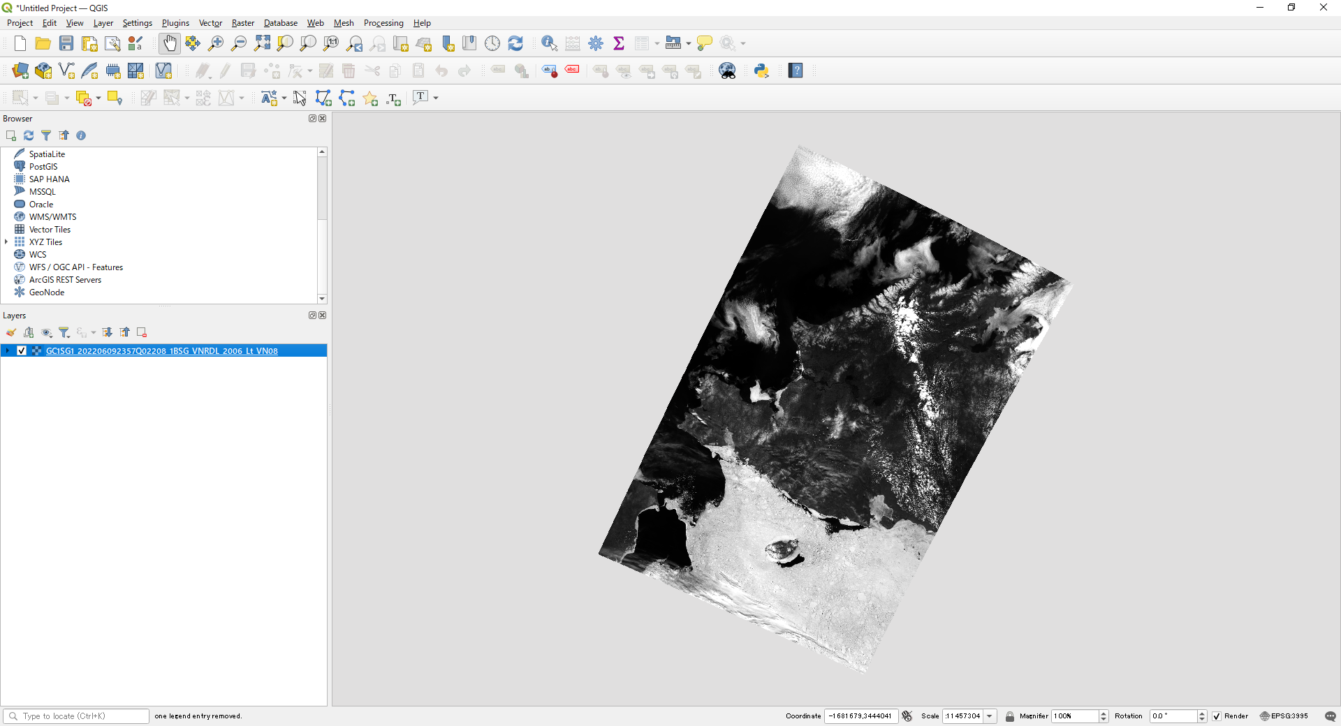
Polar area (default: Geodetic Lat/Long)

Polar area (Polar-Stereo (PS))

POL Product Area (half-path)

POL tilt drive before/after (default)

Before POL tilt drive

After POL tilt drive

This section explains converting a GeoTIFF file using the "Tools used" above and the HDF5 sample data below.

Data used in the explanation

Please obtain the following data from G-Portal.

Level-1B VNR:
Observed 04/30/2022 Around Japan Daytime
GC1SG1_202204300131L05110_1BSG_VNRDQ_2005.h5(665MB)

Level-1B IRS:
Observed 04/30/2022 Around Japan Daytime
GC1SG1_202204300131L05110_1BSG_IRSDQ_2005.h5(183MB)

Level-1B POL:
Observed 04/30/2022 Around Japan Daytime
GC1SG1_202204300109N05100_1BSG_POLDK_2005.h5(670MB)

1)Command for Level-1B VNR product (single SD array) conversion

Using the Windows command prompt or the equivalent, go to the directory where "SGLI_geo_map_win.exe" is located.
(The Windows command prompt can be accessed from Windows Start > Windows System > Command Prompt)
Below is an example where SGLI_geo_map_win.exe and the data folder containing the data are in the sgli_data folder directly under the C drive with.

The command is an example of map projection of an SD array Lt_VN08 in Image_data and output as an LZW compressed GeoTIFF file.
The pixel value of 65535 is set for an invalid value, and the slope and offset values in the attribute (text information) are stored in the GDAL_METADATA tag.

>cd C:\sgli_data
>SGLI_geo_map_win.exe c:\sgli_data\data\GC1SG1_202204300131L05110_1BSG_VNRDQ_2005.h5 -d Image_data/Lt_VN08 -m -a reflectance -n 65535 -z -o c:\sgli_data

Command Explanation

For details on optional commands, please refer to the User's manual.

  • SGLI_geo_map_win.exe: SGLI Map projection & GeoTIFF conversion tool for Windows
  • c:\sgli_data\data\: The directory where the product is stored. If it is the same directory as the tool, there is no need to describe it.
  • GC1SG1_202204300131L05110_1BSG_VNRDQ_2005.h5:Product name obtained from G-Portal
  • -d Image_data/Lt_VN08: SD array names (dataset name) in Image_data to be converted
  • -m: Mask the stray-light correction flag
  • -a reflectance: Set the reflectance conversion coefficients (slope_reflectance, offset_reflectance). If the software supports it, like QGIS, the converted values will be displayed (the data will retain their original values).
  • -n 65535: Set an invalid value
  • -z: Apply LZW compression
  • -o C:\sgli_data: Set any output destination

See "GeoTIFF Tag Information" for the tag information stored in the converted GeoTIFF file.

Converted image displayed in QGIS

2) Combining multiple SD arrays of Level-1B VNR products into one file

Regarding Level-1B product, multiple SD arrays can be output to a single GeoTIFF file. For details, please refer to the user's manual.
Using the Windows command prompt or equivalent, go to the directory where "SGLI_geo_map_win.exe" is located.
(The Windows command prompt can be accessed from Windows Start > Windows System > Command Prompt)
Below is an example where SGLI_geo_map_win.exe and the data folder containing the data are in the sgli_data folder directly under the C drive.

The command is an example of map projection of SD arrays Lt_VN08, Lt_VN05, and Lt_VN03 in Image_data and output as a single LZW compressed GeoTIFF file.
The pixel value of 65535 is set for an invalid value, and the slope and offset in the attribute (text information) are stored in the GDAL_METADATA tag.

>cd C:\sgli_data
>SGLI_geo_map_win.exe c:\sgli_data\data\GC1SG1_202204300131L05110_1BSG_VNRDQ_2005.h5 -c VN08,VN05,VN03 -m -a reflectance -n 65535 -z -o c:\sgli_data

Command Explanation
  • SGLI_geo_map_win.exe: SGLI Map projection & GeoTIFF conversion tool for Windows
  • c:\sgli_data\data\: The directory where the product is stored. If it is the same directory as the tool, there is no need to describe it.
  • GC1SG1_202204300131L05110_1BSG_VNRDQ_2005.h5: Product name obtained from G-Portal
  • -c VN08,VN05,VN03: Lt_VN08, Lt_VN05, and Lt_VN03 of Image_data are output as one GeoTIFF file in RGB order.
  • -m: Mask the stray-light correction flag
  • -a reflectance: Set the reflectance conversion coefficients (slope_reflectance, offset_reflectance). If the software supports it, like QGIS, the converted values will be displayed (the data will retain their original values).
  • -n 65535: Set an invalid value
  • -z: Apply LZW compression
  • -o C:\sgli_data: Set any output destination

See "GeoTIFF Tag Information" for the tag information stored in the converted GeoTIFF file.

Converted image displayed in QGIS

3) Command for Level-1B IRS product (single SD array) conversion

Using the Windows command prompt or equivalent, go to the directory where "SGLI_geo_map_win.exe" is located.
(The Windows command prompt can be accessed from Windows Start > Windows System > Command Prompt)
Below is an example where SGLI_geo_map_win.exe and the data folder containing the data are in the sgli_data folder directly under the C drive with.

The command is an example of map projection of an SD array Lt_TI02 in Image_data and output as an LZW compressed GeoTIFF file.
The pixel value of 65535 is set for an invalid value, and the slope and offset values in the attribute (text information) are stored in the GDAL_METADATA tag.

>cd C:\sgli_data
>SGLI_geo_map_win.exe c:\sgli_data\data\GC1SG1_202204300131L05110_1BSG_IRSDQ_2005.h5 -d Image_data/Lt_TI02 -m -a default -n 65535 -o -z c:\sgli_data

Command Explanation

For details on optional commands, please refer to the User's manual.

  • SGLI_geo_map_win.exe: SGLI Map projection & GeoTIFF conversion Tool for Windows
  • c:\sgli_data\data\: The directory where the product is stored. If it is the same directory as the tool, there is no need to describe it.
  • GC1SG1_202204300131L05110_1BSG_IRSDQ_2005.h5: Product name obtained from G-Portal
  • -d Image_data/Lt_TI02: SD array name (dataset name) in Image_data to be converted
  • -m: Mask the stray-light correction flag
  • -a default: Set the radiance conversion coefficients (slope, offset). TIR has only radiance values, while SWI also has reflectance conversion coefficients. If the software supports it, like QGIS, the converted values will be displayed (the data will retain their original values).
  • -n 65535: Set an invalid value
  • -z: Apply LZW compression
  • -o C:\sgli_data: Set any output destination

Converted image displayed in QGIS

4)Command for Level-1B POL product (single SD array) conversion

Using the Windows command prompt or equivalent, go to the directory where "SGLI_geo_map_win.exe" is located.
(The Windows command prompt can be accessed from Windows Start > Windows System > Command Prompt)
Below is an example where SGLI_geo_map_win.exe and the data folder containing the data are in the sgli_data folder directly under the C drive.

The command is an example of map projection of an SD array Lt_PI02 in Image_data and output as an LZW compressed GeoTIFF file.
The pixel value of 65535 is set for an invalid value, and the slope and offset values in the attribute (text information) are stored in the GDAL_METADATA tag.

>cd C:\sgli_data
>SGLI_geo_map_win.exe c:\sgli_data\data\GC1SG1_202204300109N05100_1BSG_POLDK_2005.h5 -d Image_data/Lt_PI02 -a reflectance -u 45 -l 30 -n 65535 -z -o c:\sgli_data

Command Explanation

For details on optional commands, please refer to the User's manual.

  • SGLI_geo_map_win.exe: SGLI Map projection & GeoTIFF conversion Tool for Windows
  • c:\sgli_data\data\: The directory where the product is stored. If it is the same directory as the tool, there is no need to describe it.
  • GC1SG1_202204300109N05100_1BSG_POLDK_2005.h5: Product name obtained from G-Portal
  • -d Image_data/Lt_PI02: SD array name (dataset name) in Image_data to be converted. No mask processing setting is required for I, Q, or U components, but for 0, m60, and p60, set mask processing (-m).
  • -a reflectance: Set the reflectance conversion coefficients (slope_reflectance, offset_reflectance). If the software supports it, like QGIS, the converted values will be displayed (the data will retain their original values).
  • -u 45 -l 30: Set the cutout range (north end (-u), south end (-l)) within 15 degrees.
  • -n 65535: Set an invalid value
  • -z: Apply LZW compression
  • -o C:\sgli_data: Set any output destination

Converted image displayed in QGIS

5) How to confirm SD array names of Level-1B products

For SD array names, please refer to "SD Array Names of Level-1B Products" below.

The SD array can be checked in the following ways.

gdalinfo HDFView

If you have a standard installation of QGIS, please use OSGeo4W Shell.
(Start Menu > QGIS 3.22.8 > OSGeo4W Shell) for version 3.22
Go to the directory containing the data to be converted and enter gdalinfo followed by the file name.
After "Image_data/" in SUBDATASET is the SD array name; for conversion in gdal, specify the underlined part.

Example of Level-1B VNR display.
(1) SD array name in Image_data
(2) SD array name in Geometry_data

>gdalinfo GC1SG1_202204300131L05110_1BSG_VNRDQ_2005.h5

Image_data_Lt_VN08_Error_DN=65535
Image_data_Lt_VN08_Mask=16383
Image_data_Lt_VN08_Maximum_valid_DN=65533
Image_data_Lt_VN08_Minimum_valid_DN=0
Image_data_Lt_VN08_Offset=-21.299999
Image_data_Lt_VN08_Offset_reflectance=-0.045185369
Image_data_Lt_VN08_Slope=0.01560249
Image_data_Lt_VN08_Slope_reflectance=3.3098793e-05
Image_data_Lt_VN08_Unit=W/m^2/um/sr
・・・・・・
Subdatasets:
SUBDATASET_141_NAME=HDF5:"GC1SG1_202204300131L05110_1BSG_VNRDQ_2005.h5"://Image_data/Lt_VN08
SUBDATASET_141_DESC=[7820x5000] //Image_data/Lt_VN08 (16-bit unsigned integer)


6) SD array names of Level-1B products

  Product name ID Group SD array name (dataset name)
Level-1B
Visible and Near InfraRed Radiometer(non-polarization)
VNR-NP

VNR

Image_data

Lt_VN(01-11)
Land_water_flag
QA_flag

Geometry_data

Obs_time, Obs_time_VN(01-11)
Sensor_zenith, Sensor_zenith_VN(01-11)
Solar_azimuth
Solar_zenith

Visibl and Near Infrared Radiometer(polarization)
VNR-PL

POL

Image_data

Lt_P(1,2)_(0,m60,p60)
Lt_P(I,Q,U)(01,02)
Land_water_flag
QA_flag

Geometry_data

Obs_time, Obs_time_P(1,2)_(0,m60,p60)
Sensor_azimuth, Sensor_azimuth_P(1,2)_(0,m60,p60)
Sensor_zenith, Sensor_zenith_P(1,2)_(0,m60,p60)
Solar_azimuth
Solar_zenith

Infrared Scanner(thermal infrared)
IRS(SWI+TIR)

IRS

Image_data

Lt_SW(01-04)
Lt_TI(01,02)
Statistic_data_(SWI,TIR)
Land_water_flag
QA_flag

Geometry_data

Obs_time, Obs_time_SW(01-04), Obs_time_TI(01,02)
Sensor_azimuth, Sensor_azimuth_SW(01-04), Sensor_azimuth_TI(01,02)
Sensor_zenith, Sensor_zenith_SW(01-04), Sensor_zenith_TI(01,02)
Solar_azimuth
Solar_zenith

※Some SD arrays may not be included for resolution or other reasons.

7) Converting to a physical quantity

When converted to GeoTIFF using the SGLI Map projection & GeoTIFF conversion tool, the coefficients (slope/offset) of the geophysical conversion are output to an XML file created at the same time.
Display in a text editor or browser.

Below is an example of Lt_VN08 XML.
Substitute the values of <Slope> and <Offset> into the formulas in <Data_description> to convert pixel values into physical quantities.
<Data_description>TOA radiance of VN08: Lt[W/m^2/sr/um]=(DN&Mask)*Slope+Offset; TOA reflectance of VN08: rt[Lt*pi/(F0/d^2)]=(DN&Mask)*Slope_reflectance+Offset_reflectance>
<Slope>1.560249e-002</Slope>
<Offset>-2.130000e+001</Offset>
<Slope_reflectance>3.309879e-005</Slope_reflectance>
<Offset_reflectance>-4.518537e-002</Offset_reflectance>

When calculating with the gdal command, the values converted with the following command are stored.
The following is an example of reflectance (Slope_reflectance/Offset_reflectance). To convert to radiance, please use the Slope/Offset values.
The Splope_reflectance and Offset_reflectance values can remain "3.309879e-005, -4.518537e-002".

>gdal_calc -A input.tif --outfile=output.tif --type=Float32 --calc="A * 0.00003309879 - 0.04518537" --NoDataValue=65535

8) Checking the data quality flag (QA Flag)

The quality flag (QA_Flag) of the Level-1B product contains 16 bits of information on channel integrity and POL tilt drive as ON (1) and OFF (0) for each bit.
Missing value information, etc. are stored in each pixel in the data. The missing value is the same as the masked value (16383) of the stray light correction flag.
Product quality information can be found in the attribute information in the data or the SGLI Level 1 Product Format Specification (https://gportal.jaxa.jp/gpr/information/tool GCOM-C Related Documents and Guidance).
The method to check the attributes in the data with gdalinfo of the gdal command is the same as the above "5) How to confirm SD array names of Level-1B products".

Bit No. 15 14 13 12 11 10 9 8 7 6 5 4 3 2 1 0
Example 0 1 0 0 0 0 0 1 0 0 0 0 0 0 0 0

9)GeoTIFF Tag Information

Classification Tag ID Name Definition/Value
TIFF Field
258

BitPerSample

Number of bits per component.

8 or 16
32(when converting physical quantity)

259

Compression

Compression method

1: No compression
5: LZW(when compression is specified)

257

ImageLength

Image length

Height (vertical length) of an image expressed in line units.

256

ImageWidth

Image width

Width (horizontal length) of an image expressed in pixel units.

274

Orientation

Scanning orientation

1: TopLeft(The image is stored as it is shown)

262

PhotometricInterpretation

Photometric type

1: BlackIsZero(Display 0 in grayscale image as black)

284

PlanarConfiguration

Order of storing image data

1: Pixel priority mode (pixel-by-pixel) e.g.RGBRGBRGB……
2: Plane priority mode (plane-by-plane) e.g.RRR……GGG……BBB……

339

SampleFormat

Type of data

1: Unsigned integer data
3: single precision floating point number (when converting physical quantity)

277

SamplesPerPixel

Number of samples per pixel

Number of stored channels/band

278

RowsPerStrip

The number of lines per strip

The number of lines of image data per strip.

42112

GDAL_METADATA

GDAL_METADATA

The slope and offset values are stored according to the settings.

42113

GDAL_NODATA

GDAL_NODATA

Used in the GDAL library and treated as transparent.
GeoKey
34735

GeoKeyDirectoryTag

GeoKey Directory

Store GeoKey directory

34736

GeoDoubleParamsTag

GeoDouble parameter

Stores double-valued GeoKeys

34737

GeoAsciiParamsTag

GeoAscii Parameters

Stores ASCII-valued GeoKeys

33922

ModelTiepointTag

Tie point

Tie point information(I,J,K,X,Y,Z). Image position (I,J,K) and geographic coordinates (X,Y,Z)

33550

ModelPixelScaleTag

Pixel scale in map linear units per pixel

Horizontal and vertical pixel spacing
(ScaleX, ScaleY, ScaleZ)

1024

GTModelTypeGeoKey

Type of geographic coordinate information

1: ModelTypeProjected(Projected coordinate system)
2: ModelTypeGeographic(Latitude-longitude coordinate system)

1025

GTRasterTypeGeoKey

Type of raster

1: RasterPixelIsArea (One pixel represents an area in the real world)

1026

GTCitationGeoKey

CRS Citation

Geographic (Lat/Lon) / WGS84 PS / WGS84 (When PS is selected)

2054

GeogAngularUnitsGeoKey

Coordinate unit(angle) identification code.

9102: Degree

2048

GeographicTypeGeoKey

Type of coordinate system

4326: WGS84

2049

GeogCitationGeoKey

Geographic coordinate system citation

WGS 84 (When converted by gdal)

3072

ProjectedCSTypeGeoKey

Projected coordinate reference system

32767: User-defined (When PS is selected)

3073

PCSCitationGeoKey

Projection citation

Geographic (Lat/Lon) / WGS84 PS / WGS84 (When PS is selected)

3074

ProjectionGeoKey

Projection method

32767: User-defined (When PS is selected)

3075

ProjCoordTransGeoKey

Coordinate transformation method

15: CT_PolarStereographic (When PS is selected)

3076

ProjLinearUnitsGeoKey

Linear unit

9001: Linear_Meter (When PS is selected)

3081

ProjNatOriginLatGeoKey

Latitude of map-projection Natural origin

71(Northern hemisphere), -71(Southern hemisphere) (When PS is selected)

3082

ProjFalseEastingGeoKey

Gives the easting coordinate of the map projection Natural origin

0 (When PS is selected)

3083

ProjFalseNorthingGeoKey

Gives the northing coordinate of the map projection Natural origin

0 (When PS is selected)

3095

ProjStraightVertPoleLongGeoKey

Longitude at Straight Vertical Pole. For polar stereographic

0 (When PS is selected)