- TOP >
- SHIKISAI GeoTIFF >
- SHIKISAI GeoTIFF-Ocean
SHIKISAI GeoTIFF-Ocean | Atmosphere | Cryosphere | Land | Level1B
Level-2 / Level-3 Ocean Products
Click on the product name to see the details of the product.
If there are SD arrays (data sets) for multiple observation wavelengths, a representative one is shown.
<Sea Surface Temperature (SST)>
Level-2 products are provided as HDF files by scene.
Level-3 products are provided on a global basis.
G-Portal: HDF5
G-Portal Processing Request: GeoTIFF
JASMES: NetCDF4
Physical quantity
Sea Surface Temperature (SST)
Temperature of the sea surface.
Resolution
Level-2: 250m, 500m, 1km (Based on observations)
Level-3: 1/24deg (4.6km)
Level-2
Level-3
(daily statistics)
Level-3
(8-day statistics)
Level-3
(1-month statistics)
<In-water properties (IWPR) [CHLA/ TSM/ CDOM]>
Level-2 products are provided as a single HDF5 file including CHLA (Chlorophyll-a concentration), TSM (Total suspended matter), and CDOM (Colored dissolved organic matter) by scene.
Level-3 products are provided as individual physical quantity products.
G-Portal: HDF5
G-Portal Processing Request: GeoTIFF (Individual files)
JASMES: NetCDF4
Physical quantities
CHLA(Chlorophyll-a concentration)
Concentration of the green pigment in phytoplankton in sea surface layer.
Resolution
Level-2: 250m (Coastal only), 1km
Level-3: 1/24deg (4.6km)
Level-2
Level-3
(daily statistics)
Level-3
(8-day statistics)
Level-3
(1-month statistics)
Physical quantities
TSM (Total suspended matter)
Dry weight of suspended matter in a unit volume of surface water which is the sum of organics such as phytoplankton and inorganics such as soil.
Resolution
Level-2: 250m (Coastal only), 1km
Level-3: 1/24deg (4.6km)
Level-2
Level-3
(daily statistics)
Level-3
(8-day statistics)
Level-3
(1-month statistics)
Physical quantities
CDOM (Colored dissolved organic matter)
Light absorption coefficient of organics dissolved in surface water at 412 nm.
Resolution
Level-2: 250m (Coastal only), 1km
Level-3: 1/24deg (4.6km)
Level-2
Level-3
(daily statistics)
Level-3
(8-day statistics)
Level-3
(1-month statistics)
<Normalized Water Leaving Radiance (NWLR) [NWLR_XXX/ PAR/ TAUA_XXX]>
Level-2 products are provided as a single HDF5 file including NWLR_XXX (Normalized water leaving radiance), PAR (Photosynthetically available radiatioin), and TAUA_XXX (Atmospheric correction) by scene. (XXX: observed wavelength)
Level-3 products are provided as individual physical quantity products on a global basis.
G-Portal: HDF5
G-Portal Processing Request: GeoTIFF(Individual files)
JASMES: NetCDF4
Physical quantities
NWLR_XXX (Normalized water leaving radiance)
The upwelling radiance just above the sea surface.
Resolution
Level-2: 250m (Coastal only), 1km
Level-3: 1/24deg (4.6km)
Level-2
Level-3
(daily statistics)
Level-3
(8-day statistics)
Level-3
(1-month statistics)
Physical quantities
PAR (Photosynthetically available radiatioin)
Photon flux density within the visible wavelength range (400 to 700 nm) over ocean which is potencially available to plant for photosynthesis.
Resolution
Level-2: 250m (Coastal only), 1km
Level-3: 1/24deg (4.6km)
Level-2
Level-3
(daily statistics)
Level-3
(8-day statistics)
Level-3
(1-month statistics)
Physical quantities
TAUA_XXX (Atmospheric correction parameter)
Aerosol optical properties for the atmospheric correction over ocean.
Resolution
Level-2: 250m (Coastal only), 1km
Level-3: 1/24deg (4.6km)
Level-2
Level-3
(daily statistics)
Level-3
(8-day statistics)
Level-3
(1-month statistics)
The following methods are available for using GeoTIFF files of "SHIKISAI" Level-2/Level-3 data.
* How to convert standard data obtained from G-Portal using the tools
- -CUI: SGLI Map Projection & GeoTIFF Conversion Tool (The link to the download site is provided in "Tools" below.)
- -GUI: Earth Observation Data Conversion Tool(Click on the tool name to go to the download page)
* How to convert netCDF data obtained from the JASMES site to GeoTIFF
- Map-projected GeoTIFF data are available at FAI Monitor and Ibay Monitor.
- GeoTIFF can be converted by QGIS's format conversion function, etc. Global data is centered at 180deg longitude, therefore a reference coordinate system must be set if necessary.
- Please see the following FAQ for information on converting on the command line.
- https://shikisai.jaxa.jp/faq/faq0092.html
* How to obtain GeoTIFF from G-Portal processing requests
- Request processing of GeoTIFF data from the "Processing" button on the data search results.
- Please refer to the following FAQs for the products covered.
- https://shikisai.jaxa.jp/faq/faq0044.html
Tools
This section provides examples of GeoTIFF conversion of an HDF5 file "SHIKISAI image" obtained from G-Portal into a map-projected GeoTIFF file.
Click on the tool name to go to the download page.
| Target Product | Tool Name | |
|---|---|---|
Level-2 (L2) |
SGLI Map Projection & GeoTIFF conversion Tool |
Link to the "Tools & Documents" page in G-Portal. Platforms: Windows, Linux |
Level-3 (L3) |
QGIS(Quantum GIS)/gdal | Link to an external site. Platforms: Windows, Linux |
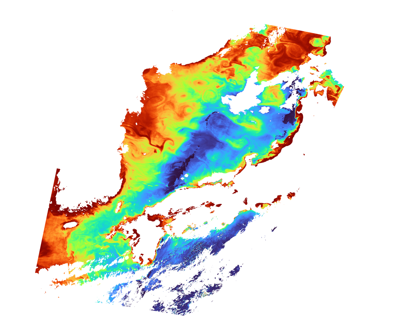
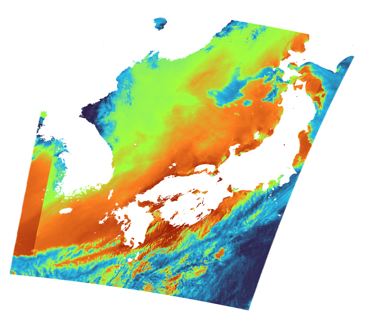
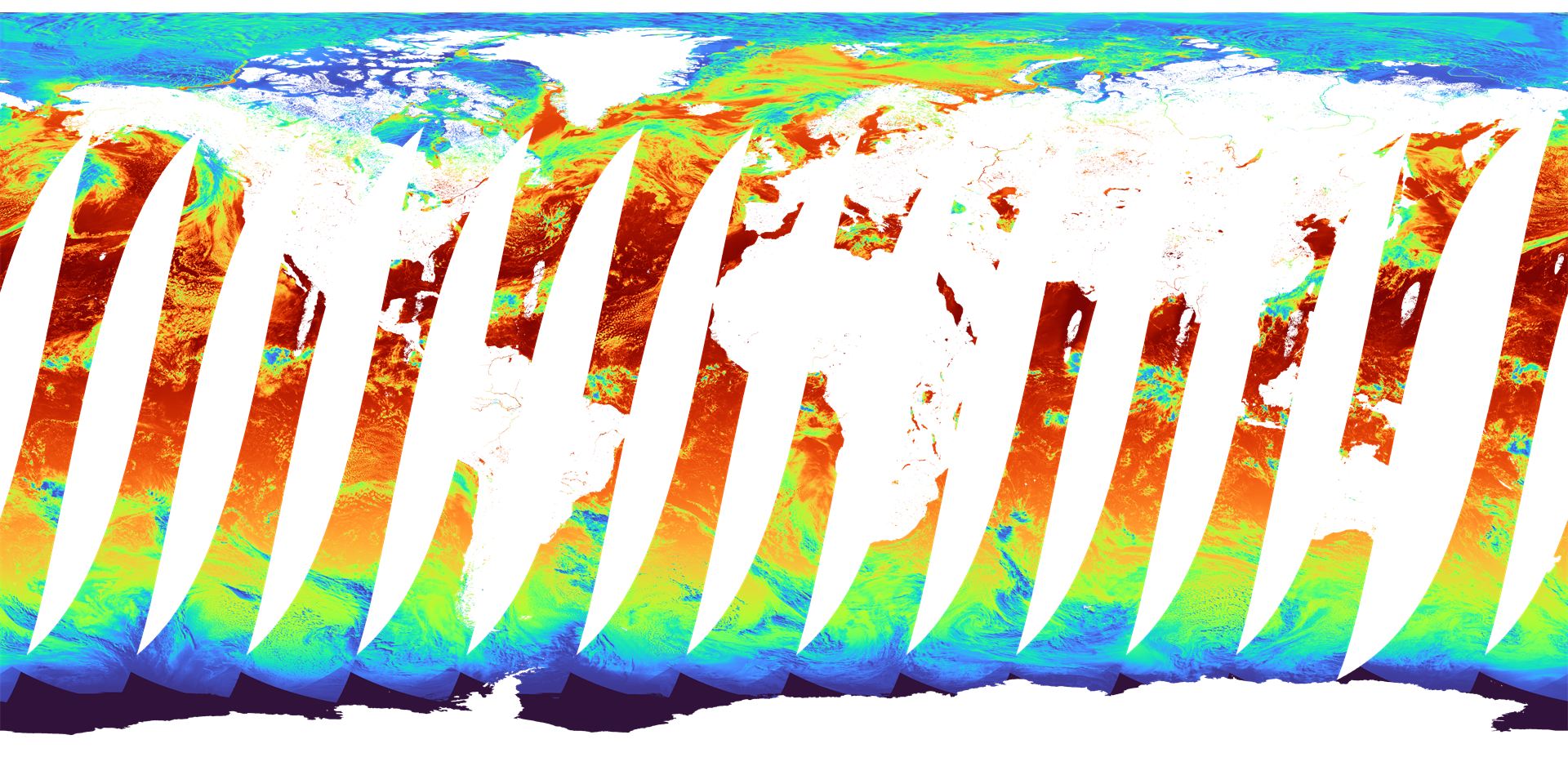
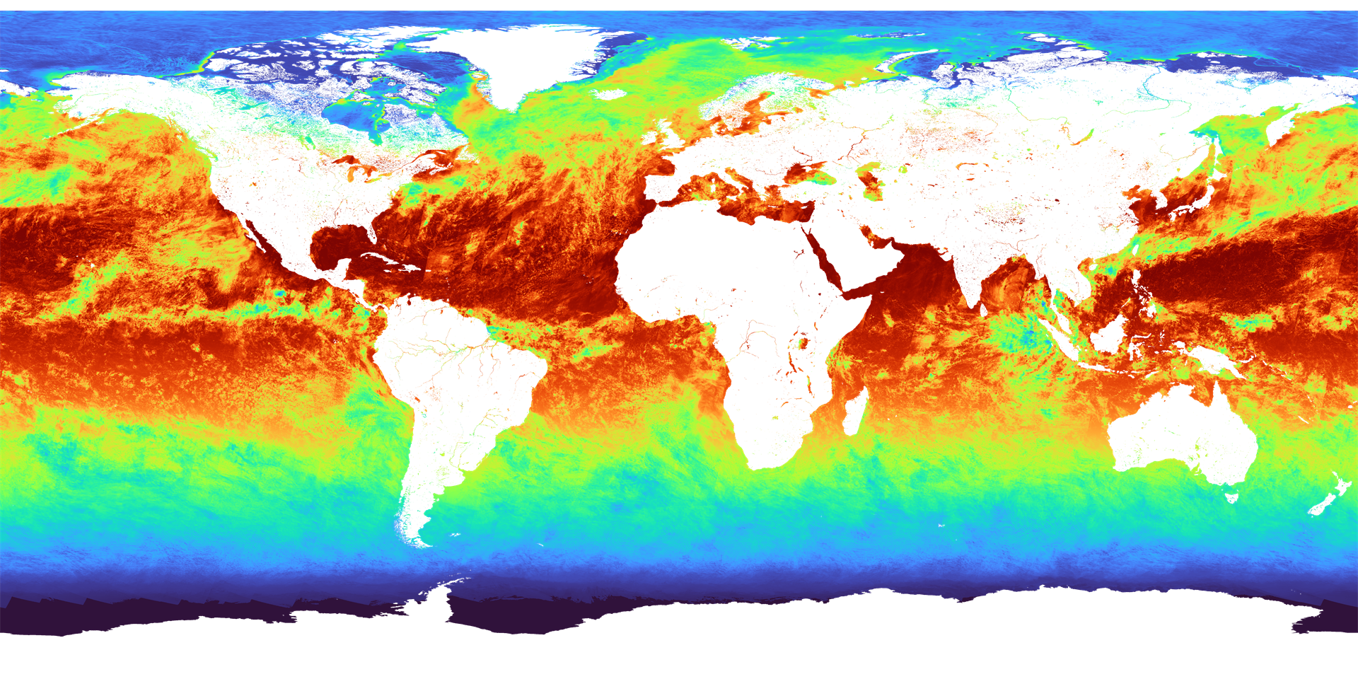
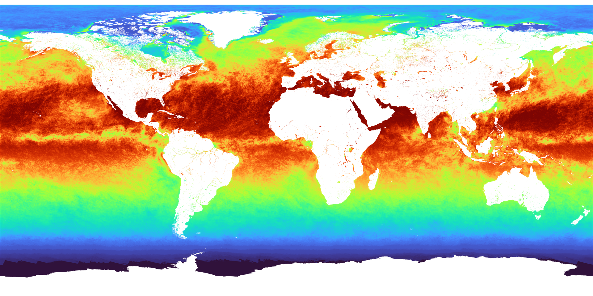
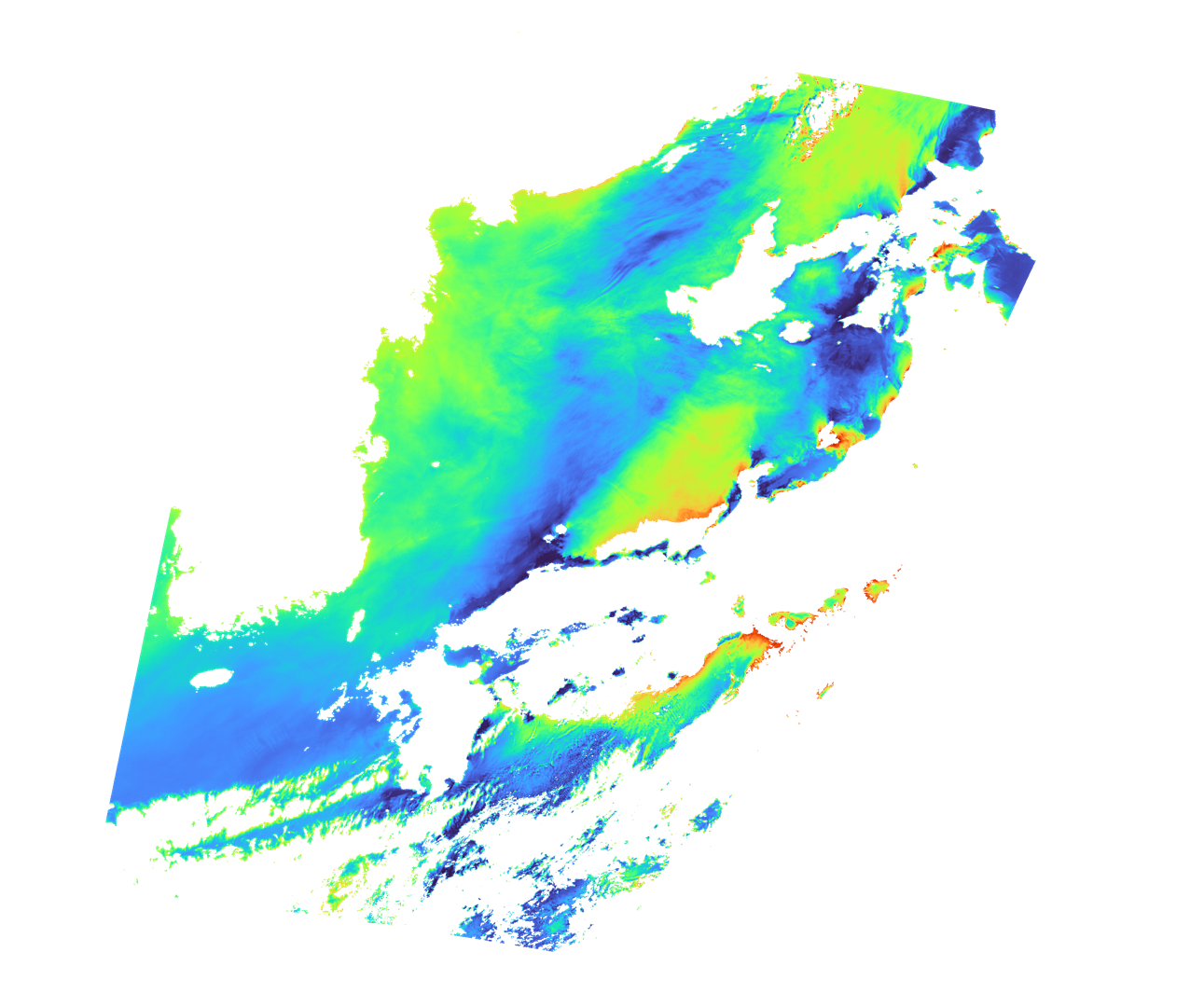
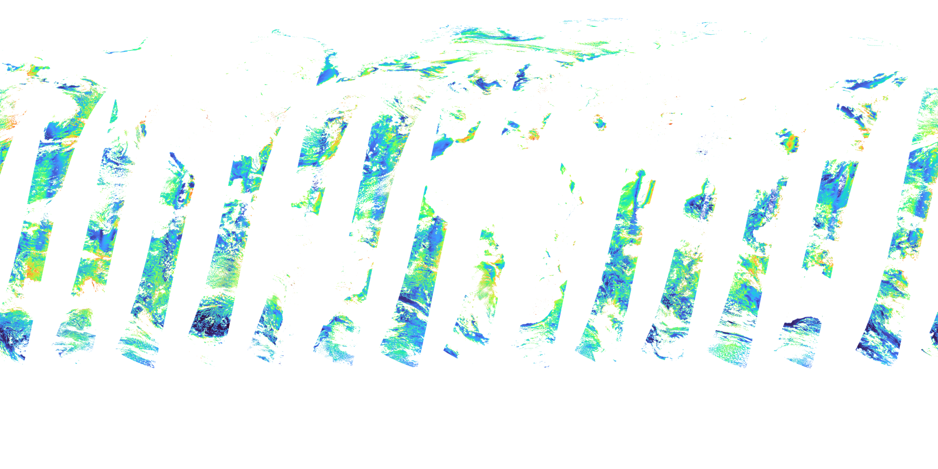
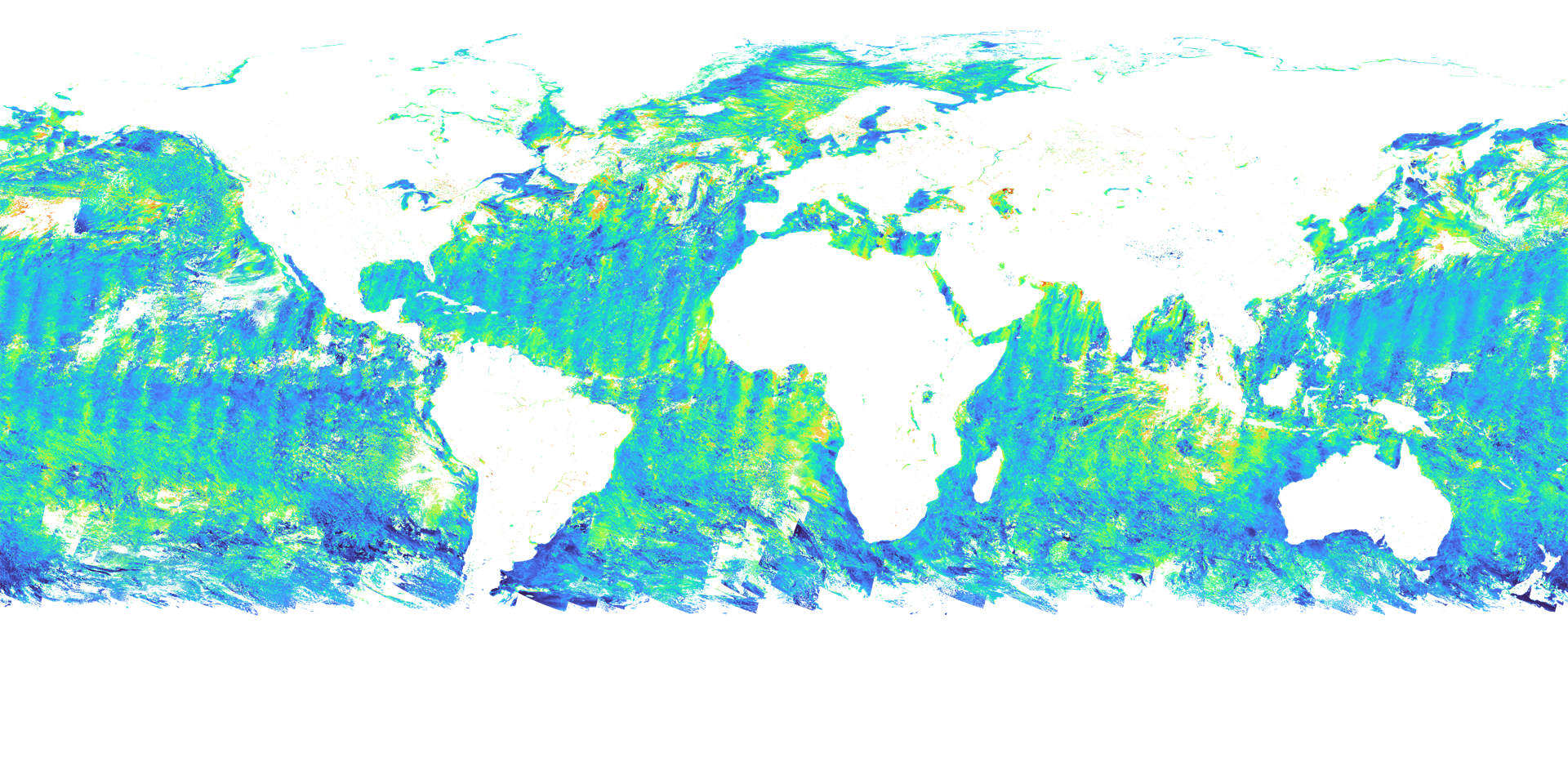
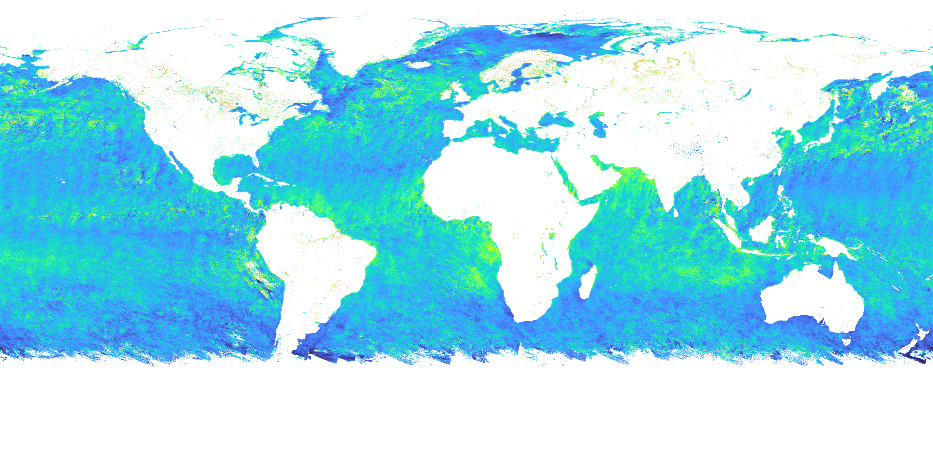
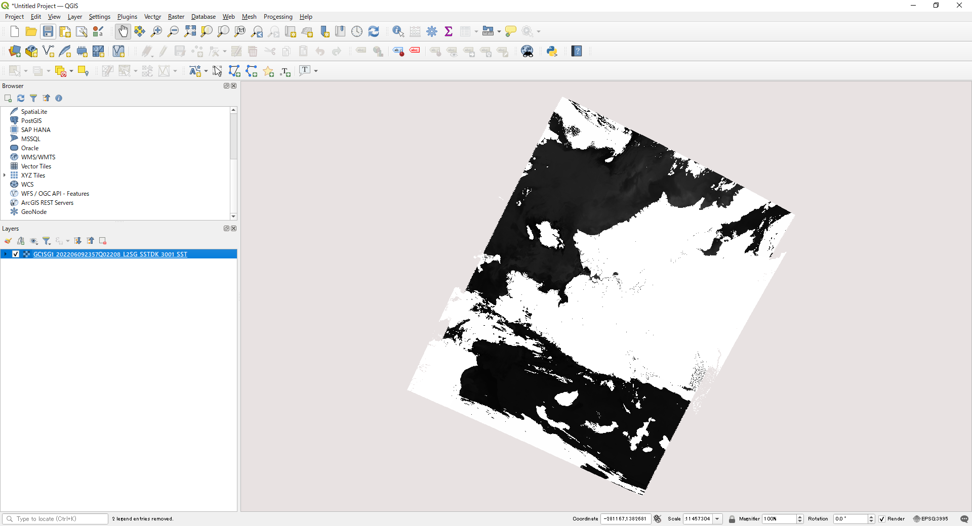
Example of GeoTIFF output from the "SGLI Map Projection & GeoTIFF Conversion Tool" and displayed in QGIS.
Descending (D) / Daytime image
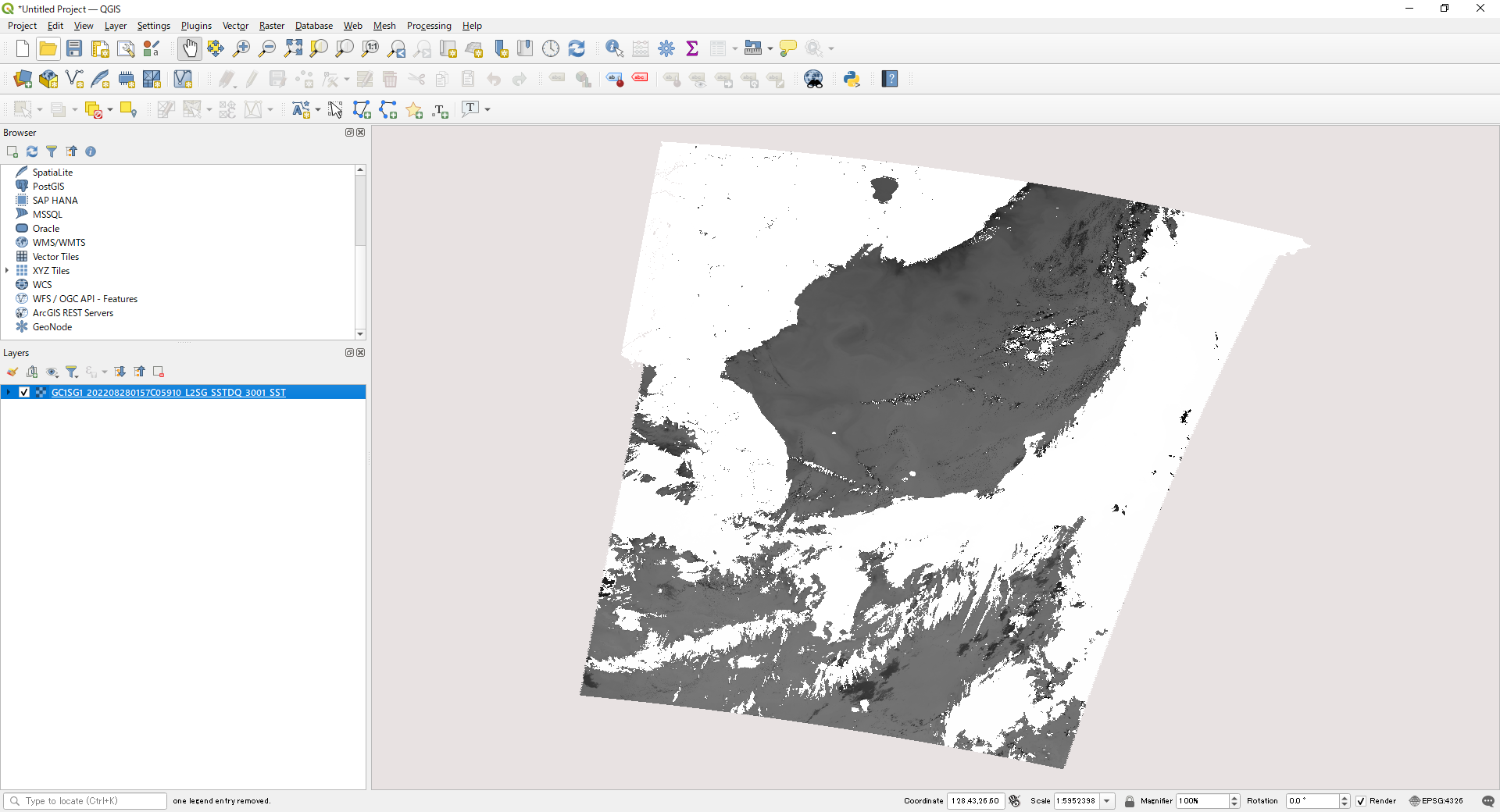
Ascending (A) / Nighttime image
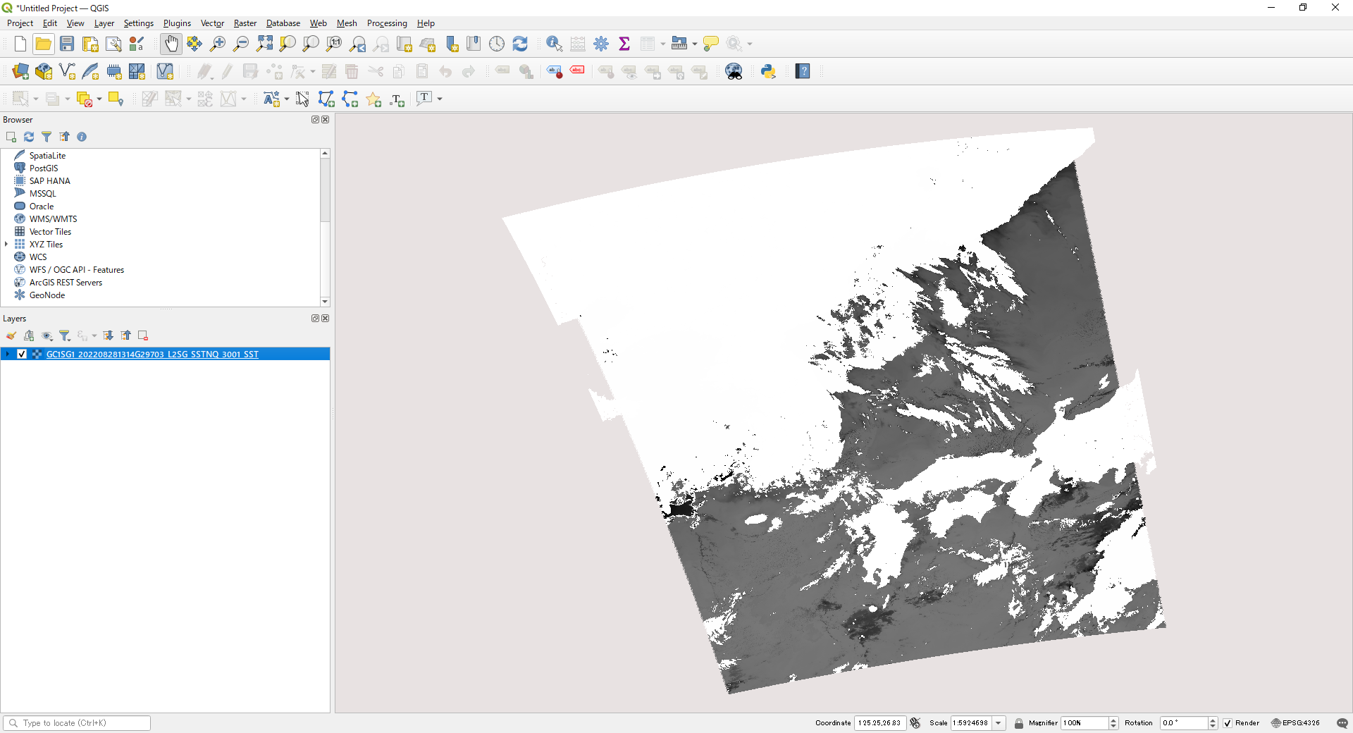
180deg crossing (default: Geodetic Lat/Long)
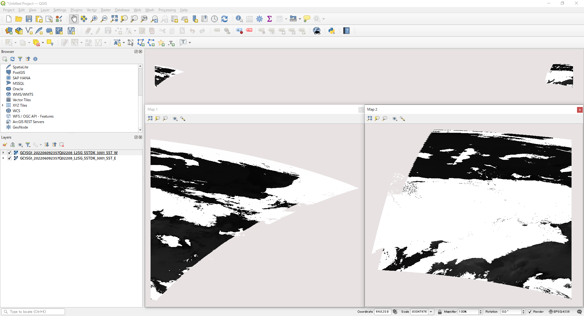
180deg crossing (Polar-Stereo (PS))
This section explains how to output a GeoTIFF file using the "Tools" above and the HDF5 sample data below.
Data used in the explanation
Please obtain the following data from G-Portal.
Level-2 SST:
Observed 09/09/2022 Around Japan Daytime
GC1SG1_202209090139J05310_L2SG_SSTDK_3001.h5 (4MB)
Level-2 NWLR:
Observed 05/18/2022 Around Japan Daytime
GC1SG1_202205180155K05910_L2SG_NWLRK_3000.h5 (17MB)
Level-3 CHLA:
Monthly statistics for July 2022 Global Daytime
GC1SG1_20220701D01M_D0000_3MSG_CHLAF_3000.h5 (19MB)
1)Command for Level-2 product (single SD array) conversion
Using the Windows command prompt or the equivalent, go to the directory where "SGLI_geo_map_win.exe" is located.
(The Windows command prompt can be accessed from Windows Start > Windows System > Command Prompt.)
Below is an example where the SGLI_geo_map_win.exe and the SST folder containing the data are in the sgli_data folder on the C drive.
The command is an example of map projection of the SD array SST in Image_data and output as an LZW compressed GeoTIFF file.
The pixel value of 65535 is set for an invalid value, and the slope and offset in the attribute (text information) are stored in the GDAL_METADATA tag.
The values can be found in the <Slope> and <Offset> tags in the XML file output with the GeoTIFF conversion.
>cd C:\sgli_data
>SGLI_geo_map_win.exe c:\sgli_data\SST\GC1SG1_202209090139J05310_L2SG_SSTDK_3001.h5 -d Image_data/SST -a default -n 65535 -z -o c:\sgli_data
For details on optional commands, please refer to the User's manual.
- SGLI_geo_map_win.exe: SGLI Map Projection & GeoTIFF Conversion Tool for Windows
- c:\sgli_data\SST\: Directory where the product is stored. If the directory is the same as where the product or tool is stored, there is no need to specify it.
- GC1SG1_202209090139J05310_L2SG_SSTDK_3001.h5: Product name obtained from G-Portal
- -d Image_data/SST: SD array name (dataset name) in Image_data to be converted
-
-a default:
Set conversion coefficients (slope/offset) for physical quantities.
There is a "reflectance" option, but the SST conversion coefficients are set to "default" because there is only one set of conversion coefficients.
If the software supports it, like QGIS, the converted values will be displayed (the data will retain their original values). - -n 65535: Set an invalid value
- -z: Apply LZW compression
- -o C:\sgli_data: Set any output destination
See "GeoTIFF Tag Information" for the tag information stored in the converted GeoTIFF file.
Since error values are not excluded in this conversion, they are set to invalid ones using per-pixel information in the XML file or SD array QA_flag created during the GeoTIFF conversion.
To create an SST image from QA_flag with less cloud influence, see the "The gdal command applying the QA_flag."
For more information on pseudo-color images, please refer to the following FAQs.
https://shikisai.jaxa.jp/faq/faq0053.html
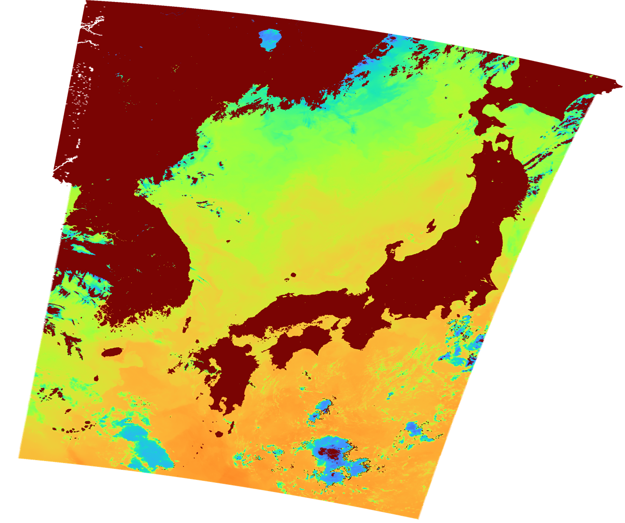
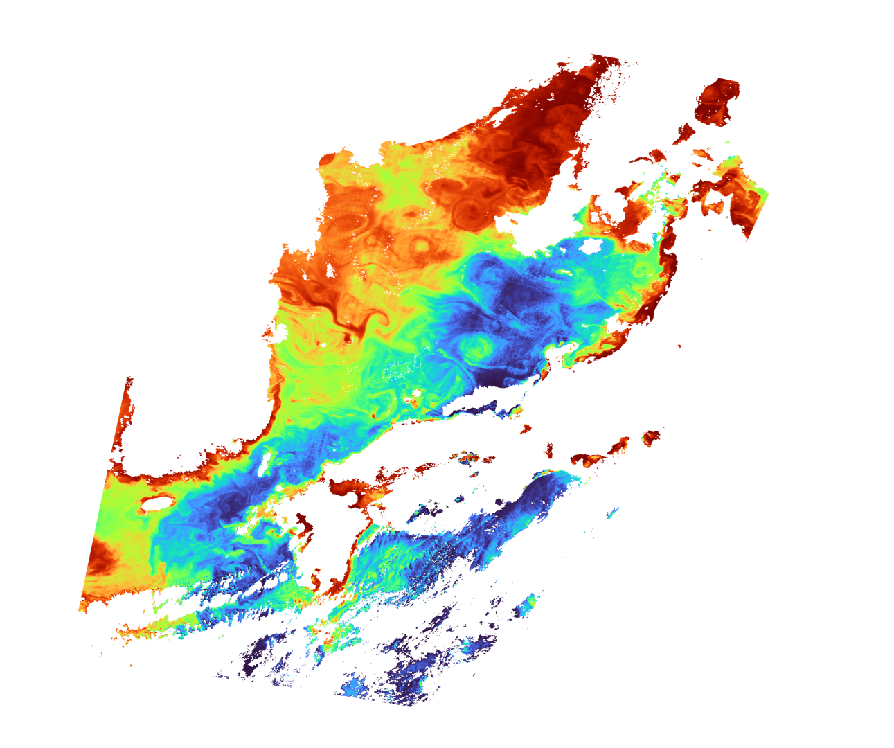
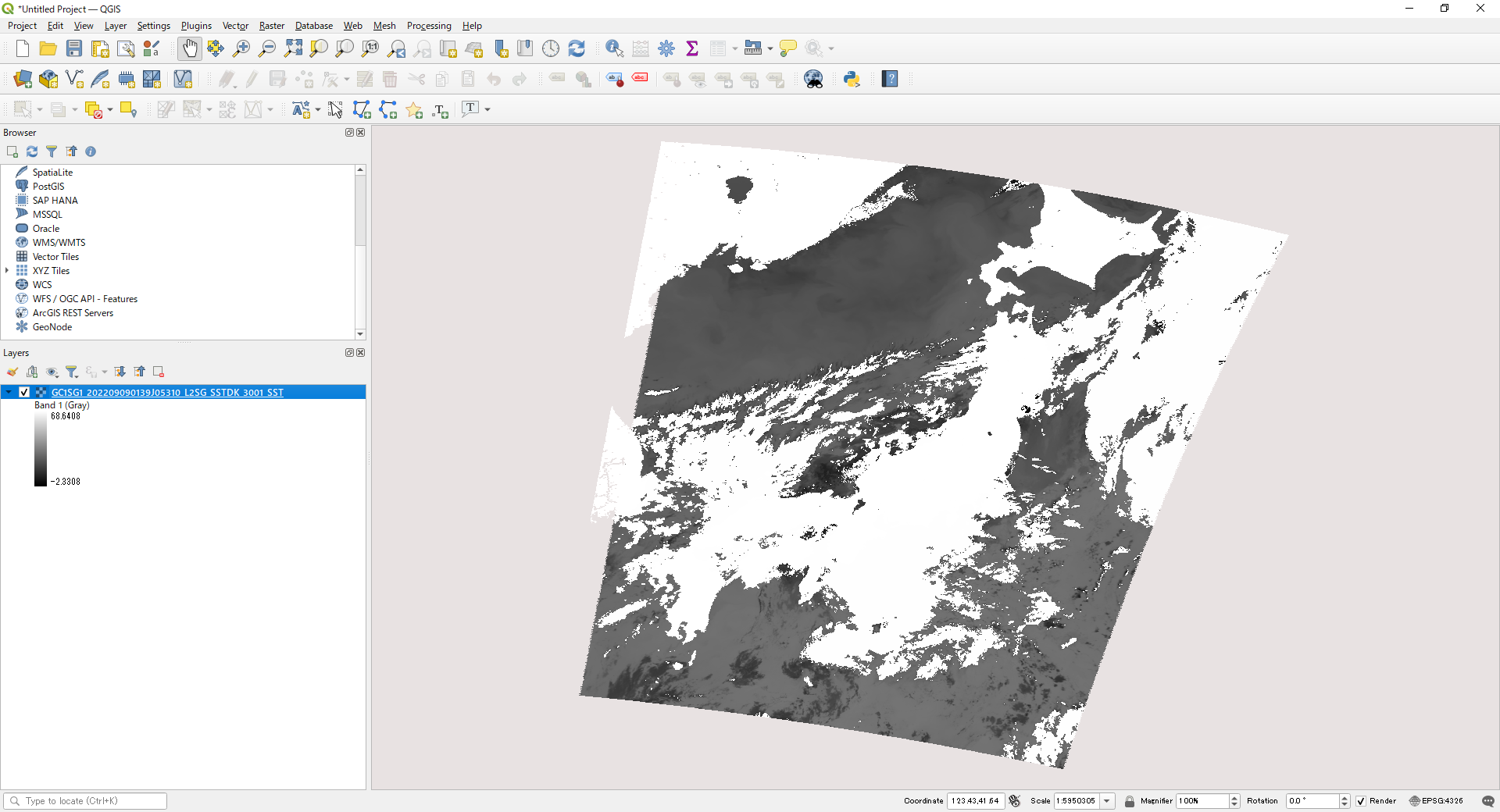
Converted image displayed in QGIS
The layer information in the lower left corner shows the values converted to temperature. Values outside the valid range are also converted.
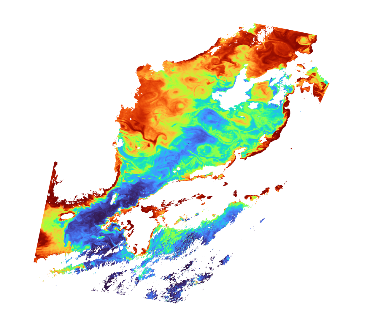
2)Combining multiple SD arrays of Level-2 products into one file
Using the Windows command prompt or the equivalent, go to the directory where "SGLI_geo_map_win.exe" is located.
(The Windows command prompt can be accessed from Windows Start > Windows System > Command Prompt.)
Below is an example where the SGLI_geo_map_win.exe and the NWLR folder containing the data are in the sgli_data folder on the C drive.
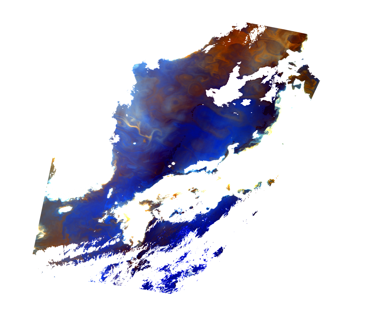
The command is an example of map projection of the SD arrays NWLR_670, NWLR_565, and NWLR_490 in the Image_data of the L2 NWLR(Normalized Water leaving radiance, etc.) product and output as GeoTIFF files, respectively.
The pixel value of 65535 is set for an invalid value and output.
The GeoTIFF files are output individually, and the gdal (QGIS) command is used to store the three files into a single GeoTIFF.
Finally, the slope and offset values in the attribute (text information) are stored in the GDAL_METADATA tag and compressed in LZW.
First, convert each Image_data SD array you wish to combine into a GeoTIFF. This is for three files for RGB compositing.
Once the conversion is complete, close the command prompt.
>cd C:\sgli_data
>SGLI_geo_map_win.exe c:\sgli_data\NWLR\GC1SG1_202205180155K05910_L2SG_NWLRK_3000.h5 -d Image_data/NWLR_490 -a default -n 65535 -o c:\sgli_data\NWLR
>SGLI_geo_map_win.exe c:\sgli_data\NWLR\GC1SG1_202205180155K05910_L2SG_NWLRK_3000.h5 -d Image_data/NWLR_565 -a default -n 65535 -o c:\sgli_data\NWLR
>SGLI_geo_map_win.exe c:\sgli_data\NWLR\GC1SG1_202205180155K05910_L2SG_NWLRK_3000.h5 -d Image_data/NWLR_670 -a default -n 65535 -o c:\sgli_data\NWLR
For details on optional commands, please refer to the User's manual.
- SGLI_geo_map_win.exe: SGLI Map Projection & GeoTIFF Conversion Tool for Windows
- c:\sgli_data\NWLR\: Directory where the product is stored. If the directory is the same as where the product or tool is stored, there is no need to specify it.
- GC1SG1_202205180155K05910_L2SG_NWLRK_3000.h5: Product name obtained from G-Portal
- -d Image_data/NWLR_XXX (XXX : Wavelength): SD array name (dataset name) in Image_data to be converted
- -a default: Set the conversion factor (slope/offset) as the physical quantity. There is a "reflectance" option, but it is set to the "default" radiance value here. The value will be reset when combined, therefore you do not need to specify it if you do not use only it. If the software supports it, like QGIS, the converted values will be displayed (the data will retain their original values).
- -n 65535: Set an invalid value
- -o C:\sgli_data: Set any output destination
See "GeoTIFF Tag Information" for the tag information stored in the converted GeoTIFF file.
Next, start the OSgeo4W Shell.
(The OSgeo4W Shell can be accessed from Windows Start > QGIS 3.22.8 > OSgeo4W Shell for a typical installation. The above GeoTIFF output tool is also available from the OSgeo4W Shell.)
The three files created above are stored by assigning red to NWLR_670, green to NWLR_565, and blue to NWLR_490.
>cd c:\sgli_data\NWLR
>gdal_merge -separate -of GTiff -a_nodata 65535 -ot UInt16 -co COMPRESS=LZW -o NWLR_R670_G565_B490.tif
GC1SG1_202205180155K05910_L2SG_NWLRK_3000_NWLR_670.tif
GC1SG1_202205180155K05910_L2SG_NWLRK_3000_NWLR_565.tif
GC1SG1_202205180155K05910_L2SG_NWLRK_3000_NWLR_490.tif
- gdal_merge: gdal command to combine multiple files
- -separate: Store files separately
- -of GTiff: Set GeoTIFF output
- -a_nodata: Set an invalid value
- -ot UInt16: Unsigned 16 bits
- -co COMPRESS=LZW: LZW compression
- -o: Specify the output file name followed by the input files in the order you wish to assign them to RGB. QA_flag files can also be stored.
The following command specifies the physical quantity's conversion factor (slope/offset).
>gdal_edit -scale 0.0012 0.0012 0.0012 -offset -10 -10 -10 NWLR_R670_G565_B490.tif
- gdal_edit: gdal command to set slope/offset in the GDAL_METADATA tag. It can also be set by gdal_translate if all values are the same.
- -scale: Set the slope values to the GDAL_METADATA tag in the order of stored RGB (1,2,3,...).
- -offset: The offset value is set to the GDAL_METADATA tag in the order of stored RGB (1,2,3,...).
- NWLR_R670_G565_B490.tif: File name to set slope/offset
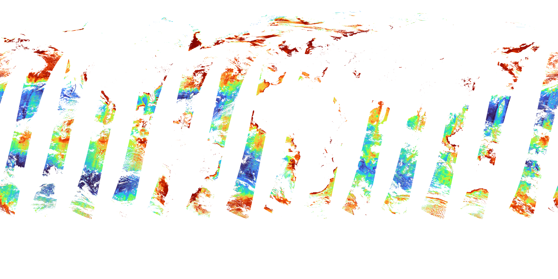
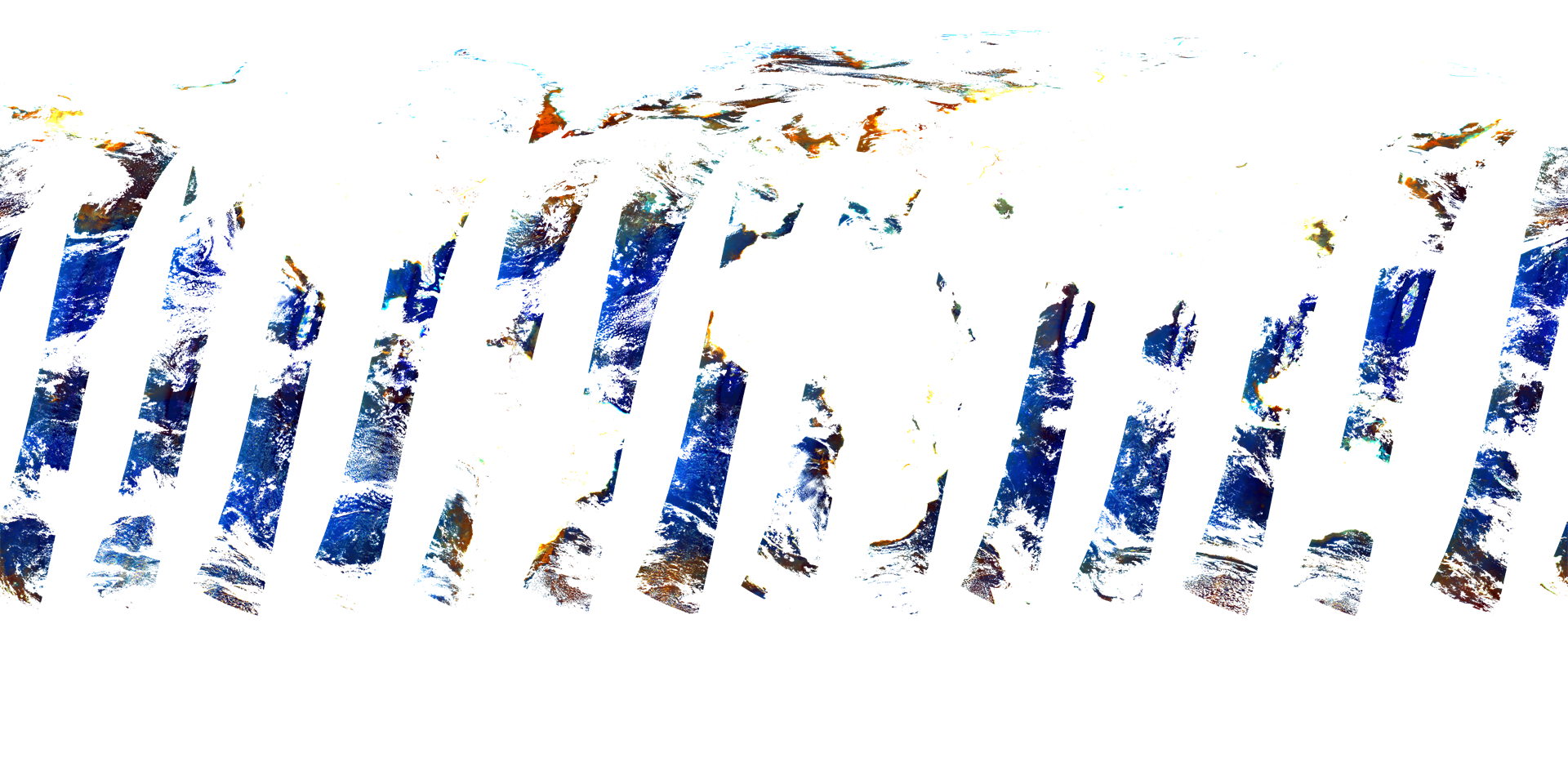
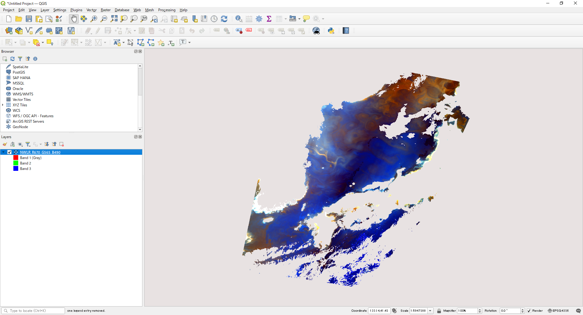
Converted image displayed in QGIS
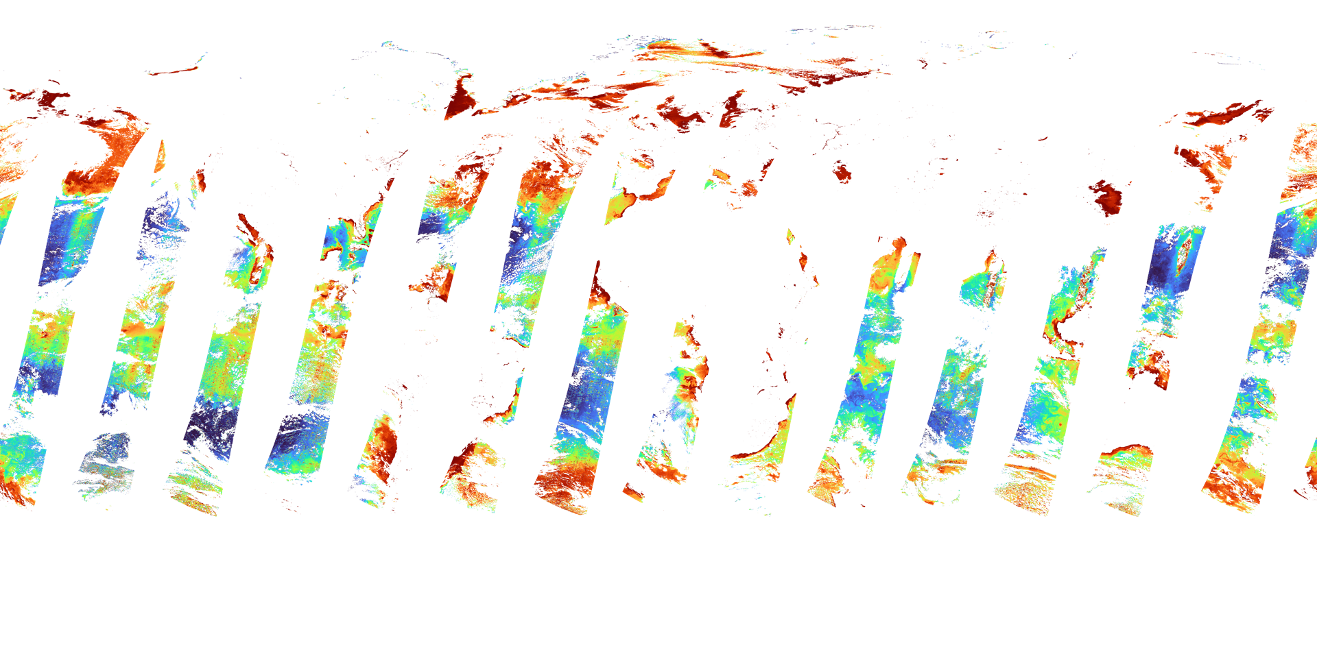
3)The gdal command during Level-3 product conversion
To use the gdal command, start the OSgeo4W Shell.
(The OSgeo4W Shell can be started from Windows Start > QGIS 3.22.8 > OSgeo4W Shell for a typical installation. The above GeoTIFF output tool is also available from the OSgeo4W Shell.)
Navigate to the directory where the data to be converted to GeoTIFF is stored.
Below is an example where the data to be converted is in the sgli_data folder on the C drive.
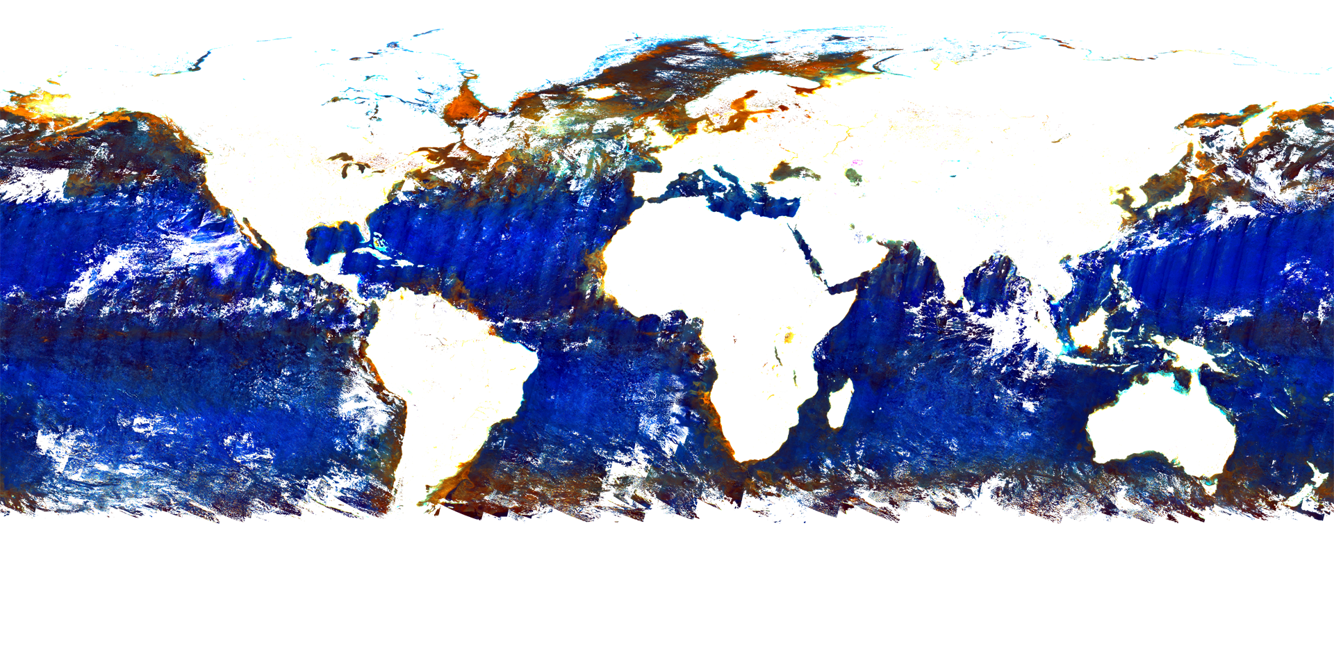
The command is an example of map projection of the SD array CHLA_AVE in Image_data and output as an LZW compressed GeoTIFF file.
The pixel value of 65535 is set for an invalid value, and the slope and offset values in the attribute (text information) are stored in the GDAL_METADATA tag.
Slope and offset values can be checked with the gdalinfo command, HDFView (tool download required), etc.
For an example, please refer to "How to confirm SD array name of Level-2/Level-3 ocean products."
>cd C:\sgli_data
>gdal_translate -of GTiff -a_srs EPSG:4326 -a_ullr -180 90 180 -90 -a_nodata 65535 -a_scale 0.0016 -a_offset 0 -co
COMPRESS=LZW HDF5:"GC1SG1_20220701D01M_D0000_3MSG_CHLAF_3000.h5"://Image_data/CHLA_AVE L3CHLA_output.tif
- gdal_translate: Format conversion commands
- -of GTiff: Set GeoTIFF output
- -a_srs EPSG:4326: Set the reference coordinate system for the input file.
- -a_ullr -180 90 180 -90: Set the upper left and lower right coordinate values (longitude and latitude).
- -a_nodata 65535: Set an invalid value
- -a_scale, -a_offset: Set the slope and offset values.
- -co COMPRESS=LZW: Set LZW compression.
- HDF5:"GC1SG1_20220701D01M_D0000_3MSG_CHLAF_3000.h5"://Image_data/CHLA_AVE: Information on SUBDATASET_X_NAME to be converted when displayed in gdalinfo (X: number)
- L3CHLA_output.tif: Set the output file name.
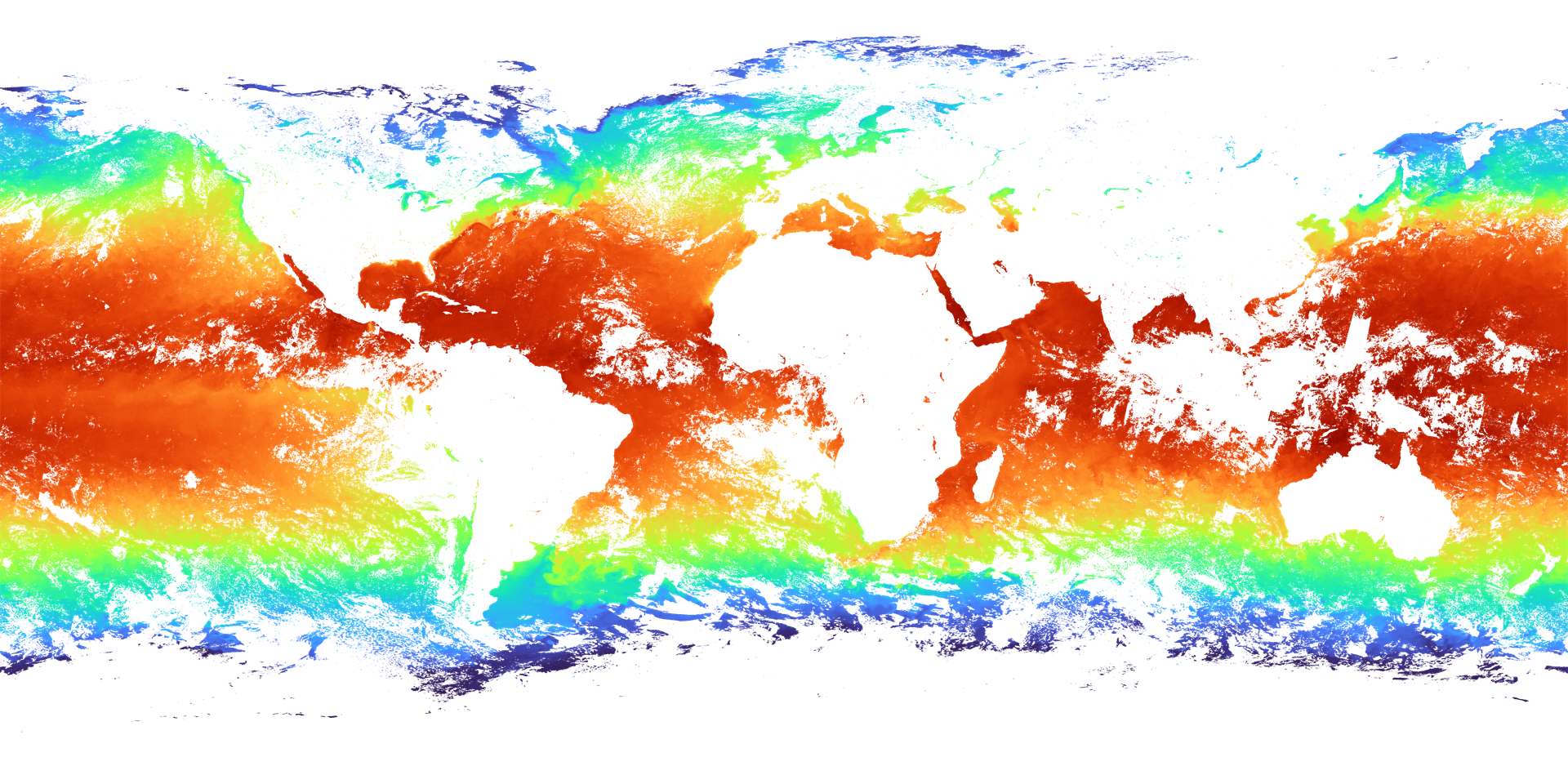
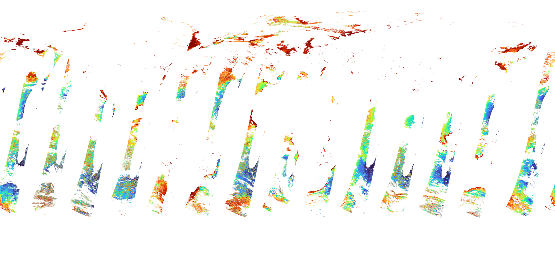
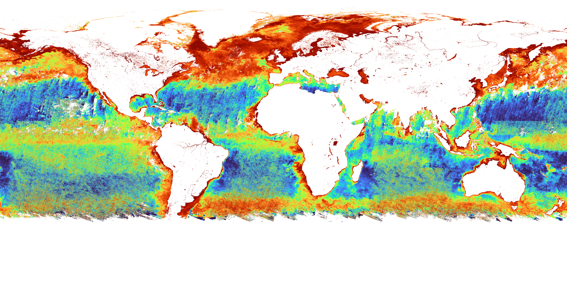
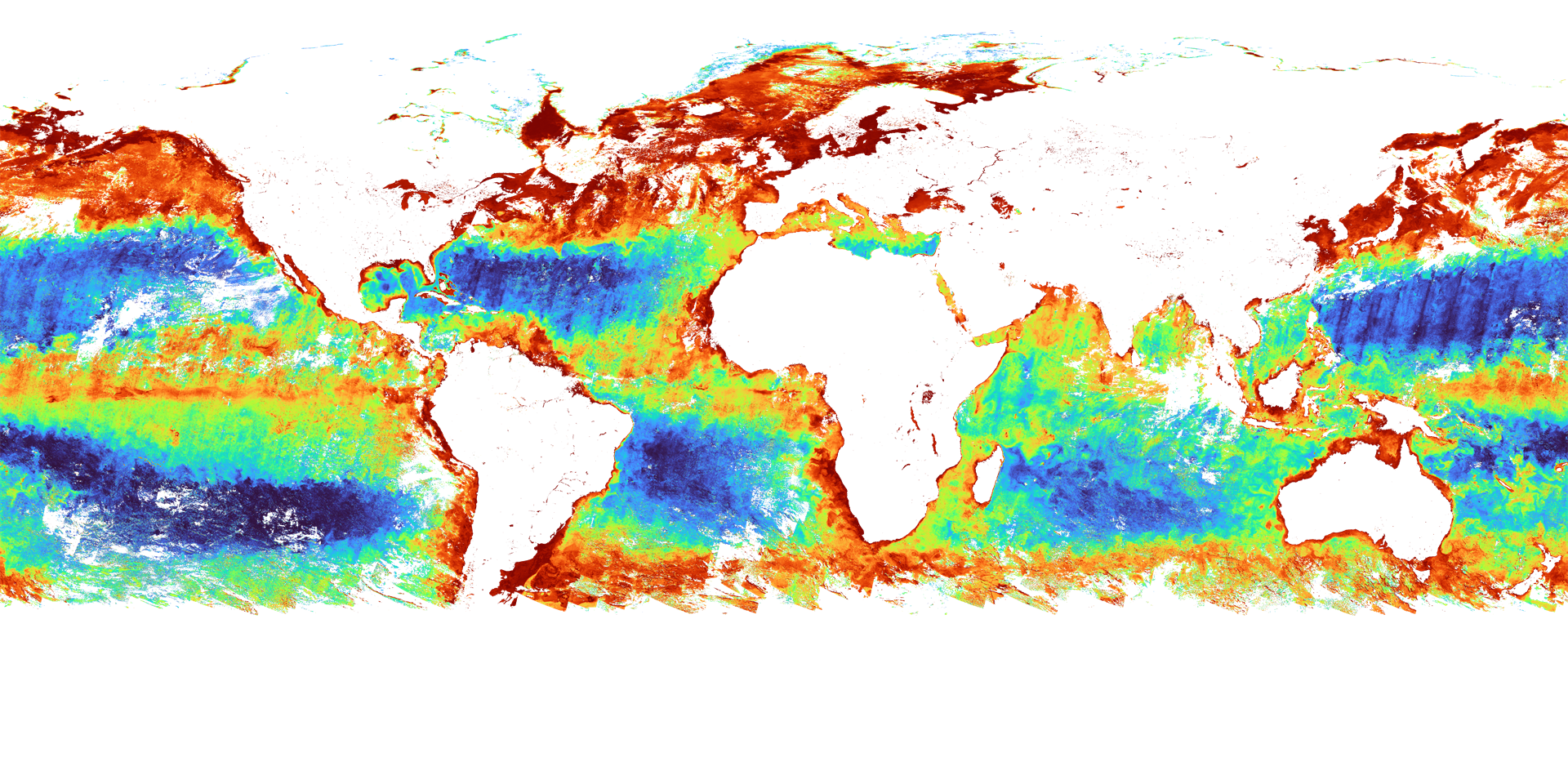
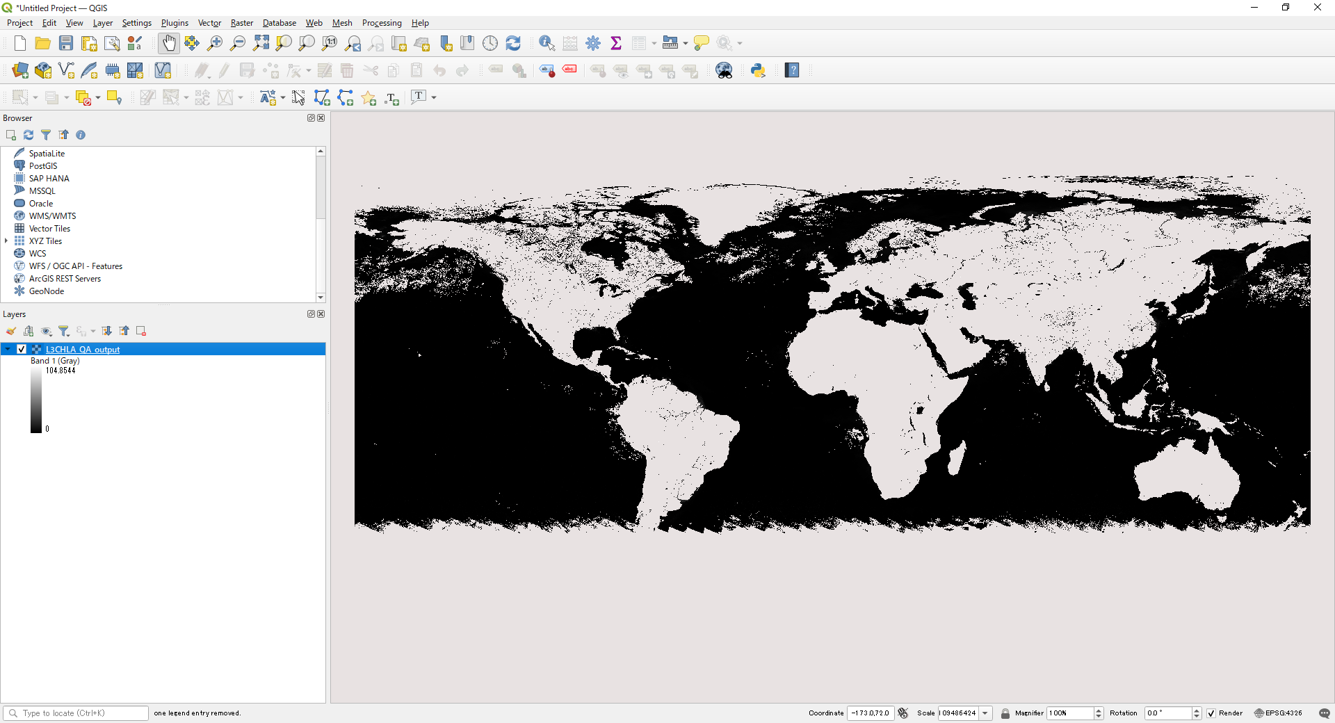
Converted image displayed in QGIS
The layer information in the lower left corner shows the value converted to a geophysical quantity (mg m^-3).

4)The gdal command for applying QA_flag to Level-2/Level-3 products
Here is an example of applying QA_flag information to SST data created with the "SGLI Map Projection & GeoTIFF Conversion Tool."
As well as SST, QA_flag in Image_data should be converted to GeoTIFF using the "SGLI Map Projection & GeoTIFF Conversion Tool."
The following command is an example of extracting data in which the 13th (Acceptable) and 14th (Good) bit flags in one pixel set in QA of SST are "1." Flags are "0" or "1."
Information on SST's QA_flag can be found in the "Products and Algorithms" section of the EORC GCOM-C website ( https://suzaku.eorc.jaxa.jp/GCOM_C/data/update/Algorithm_SST_en.html).
>cd C:\sgli_data
>gdal_calc -A GC1SG1_202209090139J05310_L2SG_SSTDK_3001_QA_flag.tif --outfile=SST_QA_flag.tif --calc="(bitwise_and(right_shift(A, 13), 3) > 0) * 1" --NoDataValue=65535
- gdal_calc: gdal command to perform calculations on the data
- -A: Set the file name used in the formula to "A."
- GC1SG1_202209090139J05310_L2SG_SSTDK_3001_QA_flag.tif: File name to be calculated
- --outfile: Set any output file name for calculation results
- --calc: Set up calculation formulas
- right_shift: Shift bit information to the right. Leave only the upper bits.
- bitwise_and: Perform a bit AND calculation.
- --NoDataValue: Set an invalid value.
* right_shift(A, 13) ----If A has the pixel value (decimal: 18431) "01000111111111111111", it is shifted right by 13. The data will be "010." (A >> 13) can be used to replace it.
* bitwise_and(A, 3) ---- Performs a bitwise operation of "11" (decimal: 3) on the pixel value of A. Extracts bits 13 and 14 of the original data. (A & 3) can be used to replace it.
| 010 | (2) | ||
| bitwise_and | 011 | (3) | |
| --------------------- | |||
| 010 | (2) | ||
(0 and 0 --> 0, 1 and 1 -->1, 0 and 1 --> 0)
* (A > 0) * 1 ----- If the value of A is greater than "0," "1" is assigned. (A > 0) If the equation is not satisfied, the value is "0." For convenience, "*1" is set, but it does not matter if "*1" is not set because the value will be "1" if the expression is satisfied.
The created QA_flag data is used to create SST data without cloud effects.
>cd C:\sgli_data
>gdal_calc -A GC1SG1_202209090139J05310_L2SG_SSTDK_3001_SST.tif -B SST_QA_flag.tif --outfile=SST_QA.tif --calc="(A > 65531) * 65535 + (A <= 65531) * (B == 0) * 65535 + (A <= 65531) * (B == 1) * A" --NoDataValue=65535
- gdal_calc: gdal command to perform calculations on the data
- -A, -B: Set "A" and "B" as file names to be used in formulas
- GC1SG1_202209090139J05310_L2SG_SSTDK_3001_SST.tif: Set to "A" the name of the file to be calculated
- SST_QA_flag.tif: Set the file name from which flags are extracted to "B."
- --outfile: Set any output file name for calculation results
- --calc: Set up calculation formulas
- (A > 65531) * 65535: Assigns invalid values to all values other than the valid values (0 to 65531) of A data.
- (A <= 65531) * (B == 0) * 65535: Data where the A data are within the valid value and B data are "0" are assigned to the invalid value.
- (A <= 65531) * (B == 1) * A: If the A data are within the valid value and the B data are "1," the A value is left unchanged. Calculations using slope/offset are also possible.
Set slope/offset with gdal_edit.
>gdal_edit -scale 0.0012 -offset -10 SST_QA.tif
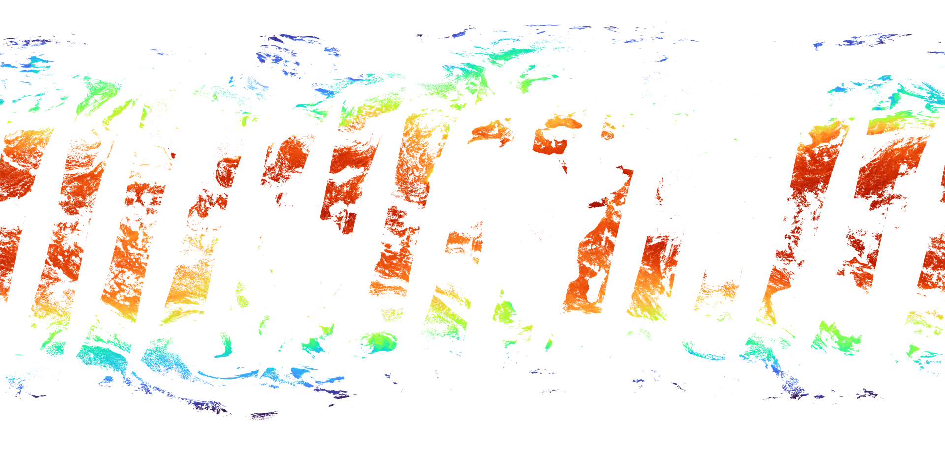
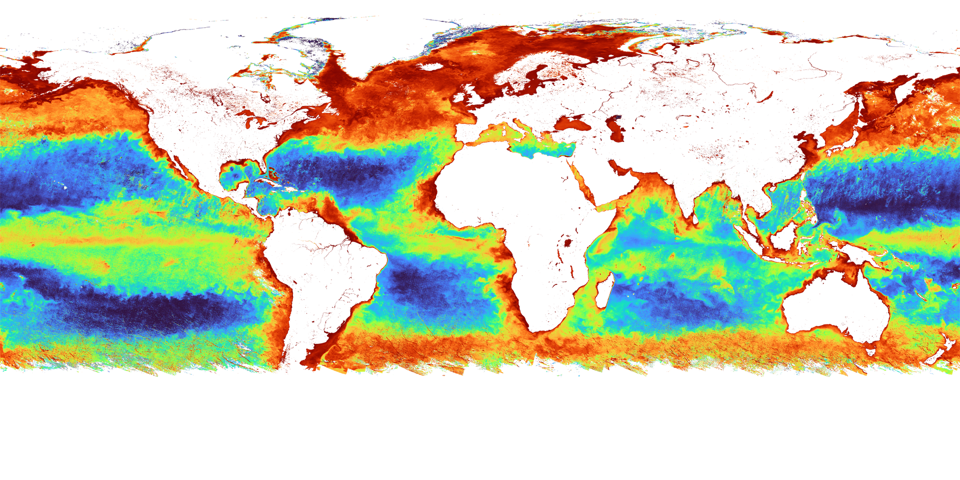
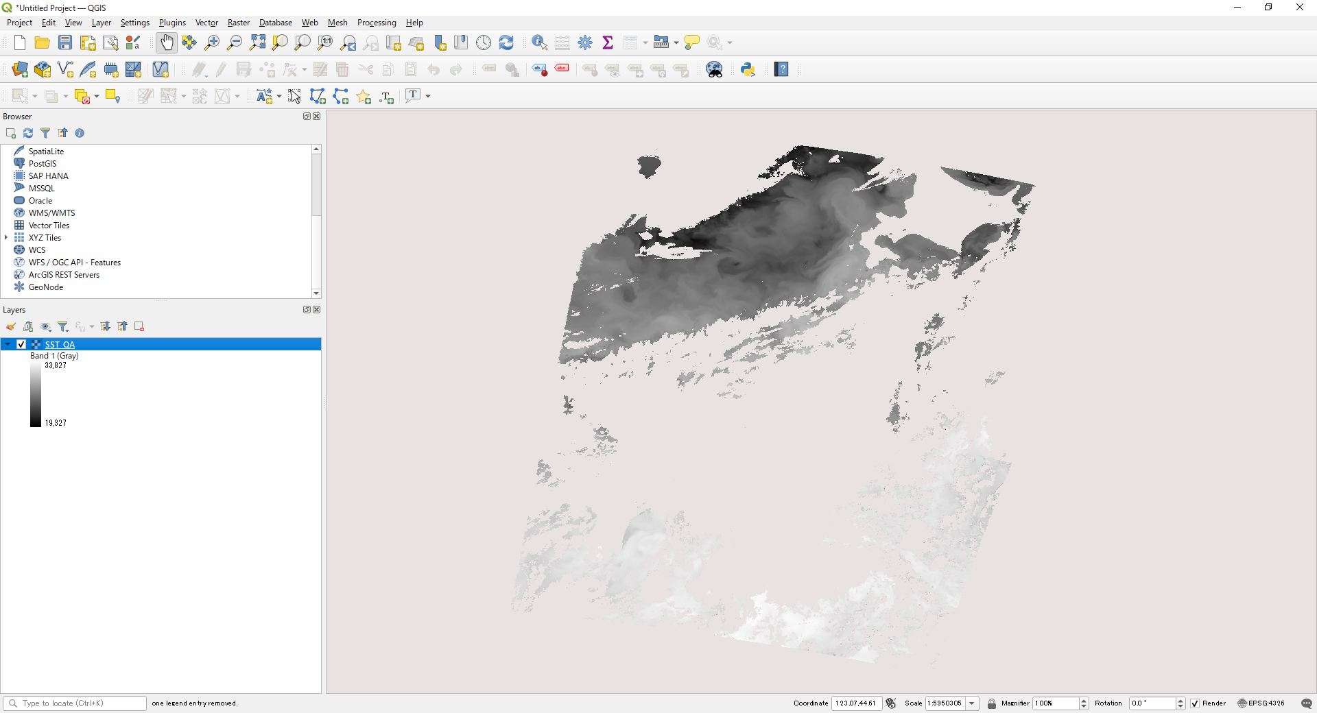
SST image with QA_flag applied in QGIS
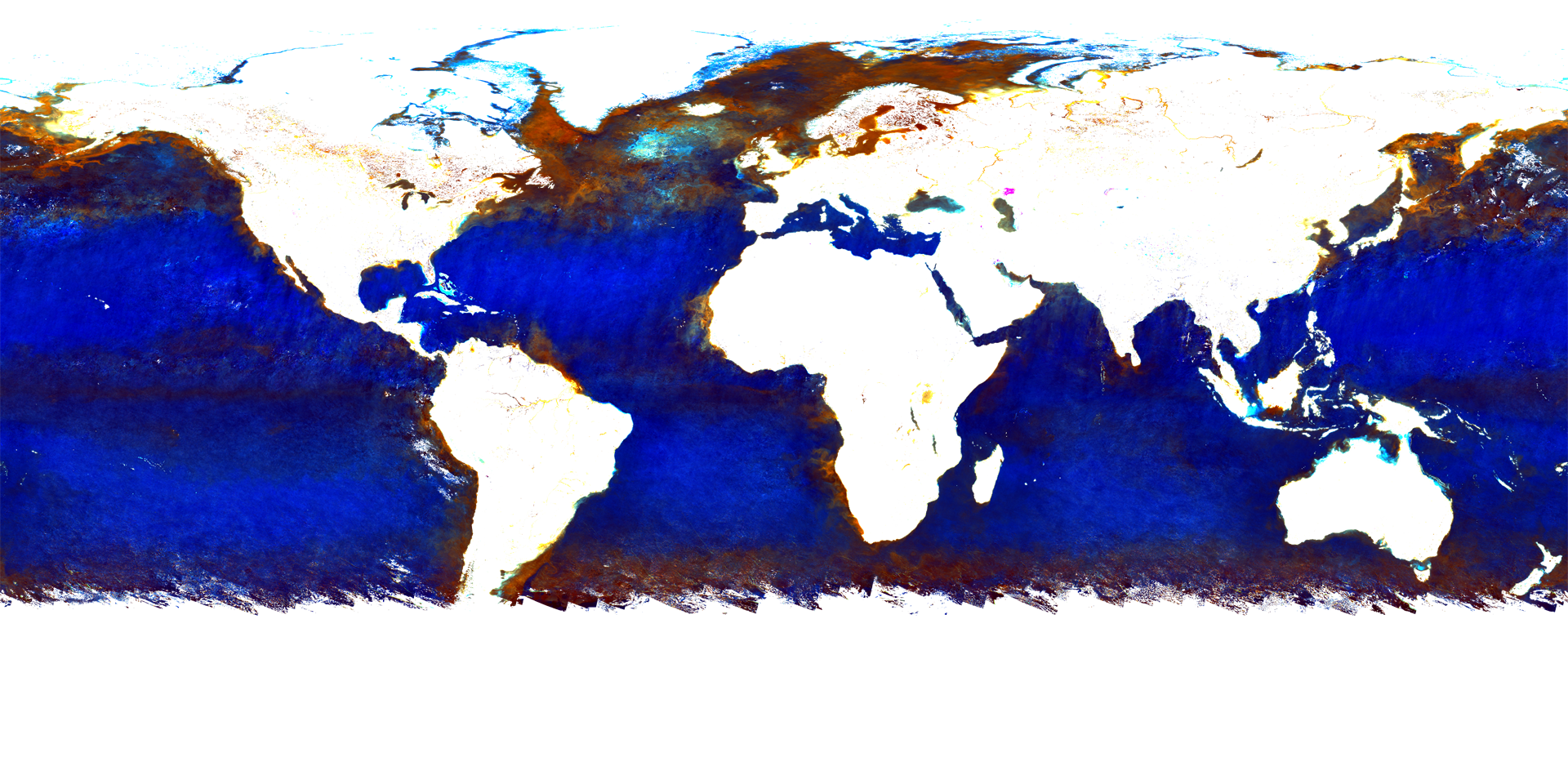
The application of QA_flag for Level-3 products is the same as for Level-2.
However, the QA_flag of L3 products is eight bits long.
The followings are examples of excluding pixels with no input data and pixels with error flags.
>gdal_translate -of GTiff -a_srs EPSG:4326 -a_ullr -180 90 180 -90 -co COMPRESS=LZW HDF5:"GC1SG1_20220701D01M_D0000_3MSG_CHLAF_3000.h5"://Image_data/CHLA_QA_flag L3CHLA_QA_flag_output.tif
>gdal_calc -A L3CHLA_QA_flag_output.tif --outfile=L3CHLA_QA_flag_output2.tif --calc="(A > 253) * 0 + (A <= 253) * 1"
>gdal_calc -A L3CHLA_output.tif -B L3CHLA_QA_flag_output2.tif --outfile=L3CHLA_QA_output.tif --calc="(A > 65534) * 65535 + (A <= 65534) * (B == 0) * 65535 + (A <= 65534) * (B == 1) * A" --NoDataValue=65535
>gdal_edit -scale 0.0016 L3CHLA_QA_output.tif
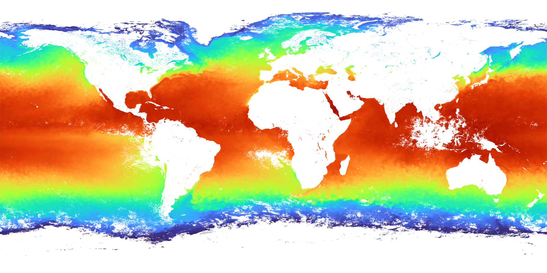
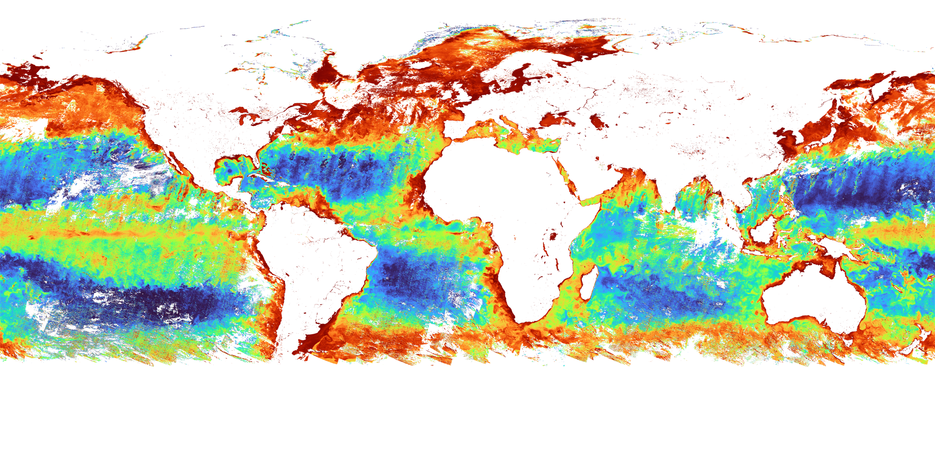
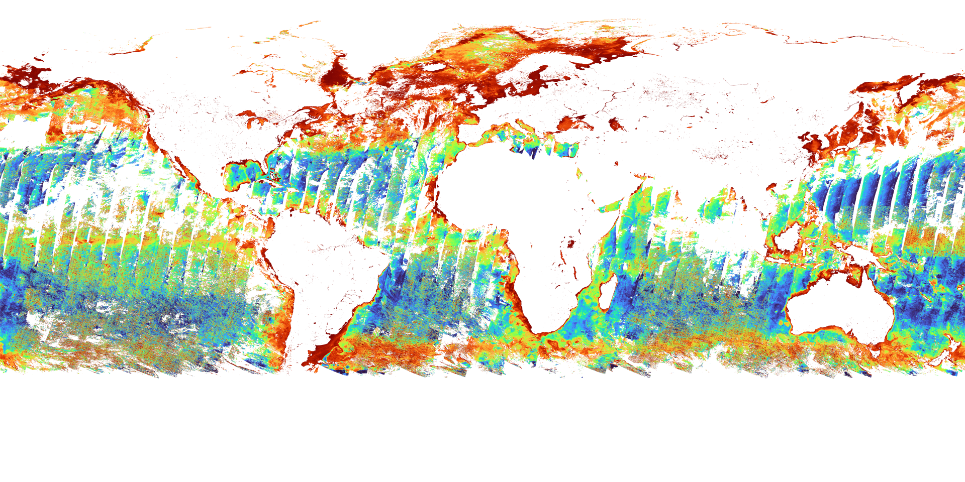
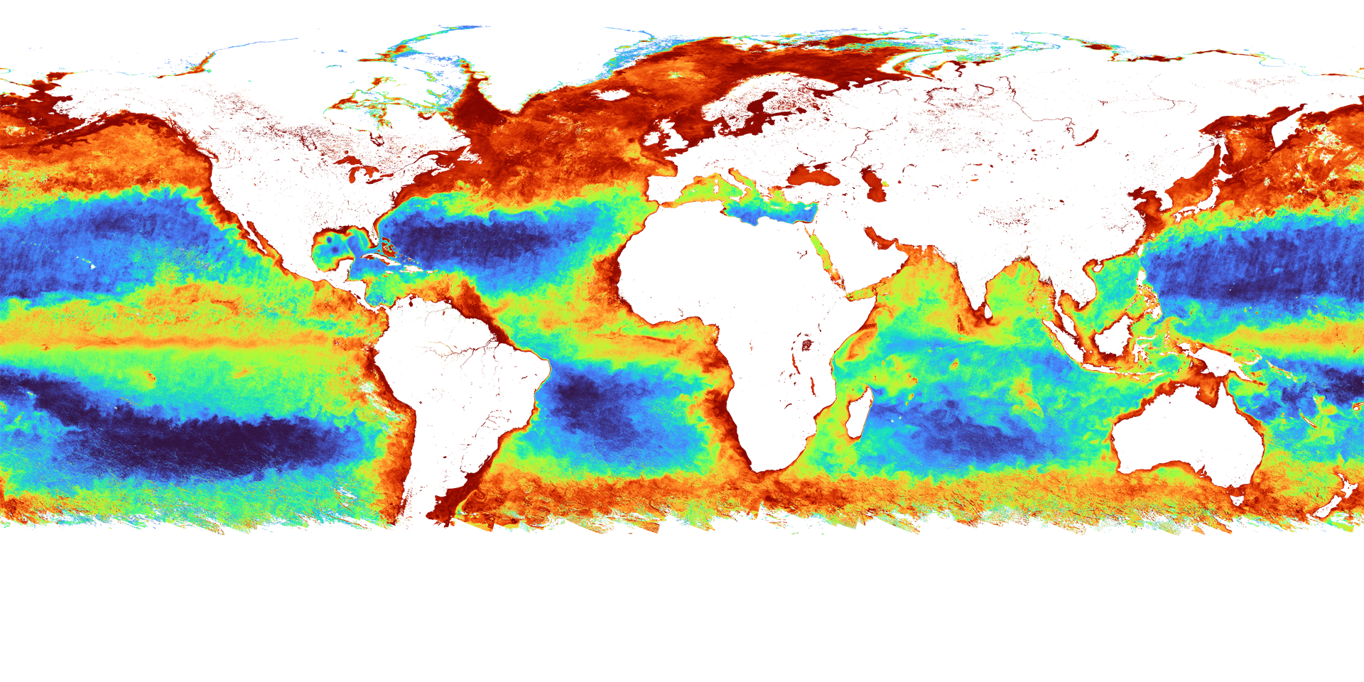
CHLA image with QA_flag applied in QGIS
5)How to confirm the SD array name of Level2/Level3 ocean products
For SD array names, please refer to "SD Array Names of Level2/Level3 Ocean Products" below.
For more information, please visit the EORC GCOM-C "Standard Products and Algorithms" website.
The SD array can be checked in the following ways.
For GeoTIFF conversion of Level 3 products, please use gdalinfo of gdal.
| gdalinfo | HDFView |
|---|---|
If you have a standard installation of QGIS, please use OSGeo4W Shell. (Start Menu > QGIS 3.22.8 > OSGeo4W Shell) for version 3.22 Go to the directory containing the data to be converted and enter gdalinfo followed by the file name. Image_data_xxx_Offset, Slope corresponds to offset, scale in gdal. After "Image_data/" in SUBDATASET is the SD array name; for conversion in gdal, specify the underlined part. |
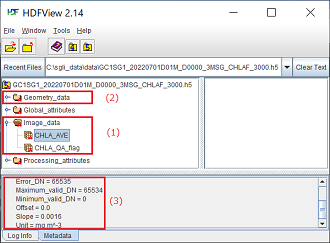
Example of Level3 CHLA display. (1)SD array name in Image_data (2)SD array name in Geometry_data (only folder if not included) (3)Additional information on CHLA_AVE, slope, offset information, etc. |
>gdalinfo GC1SG1_20220701D01M_D0000_3MSG_CHLAF_3000.h5
Image_data_CHLA_AVE_Error_DN=65535 |
|
6)SD array names of Level2 / Level3 Ocean products
| Product Name | Physical quantity | ID | SD array name(Dataset name) | |
|---|---|---|---|---|
| Level2 | NWLR (Normalized Water Leaving Radiance) |
Normalized water leaving radiance |
NWLR |
NWLR_380, NWLR_412 NWLR_443, NWLR_490 NWLR_530, NWLR_565, NWLR_670 |
Photosynthetically available radiatioin |
PAR |
|||
Atmospheric correction param |
TAUA_670, TAUA_865 |
|||
IWPR (In-water properties) |
Colored dissolved organic matter |
IWPR |
CDOM |
|
Chlorophyll-a concentration |
CHLA |
|||
Suspended solid concentration |
TSM |
|||
SST (Sea surface temperature) |
Sea surface temperature |
SST_ |
SST Cloud_probability |
|
| Level3 | NWLR (Normalized Water leaving radiance(380nm)) |
Normalized Water leaving radiance |
L380 |
L380_AVE |
NWLR (Normalized Water leaving radiance(412nm)) |
L412 |
L412_AVE |
||
NWLR (Normalized Water leaving radiance(443nm)) |
L443 |
L443_AVE |
||
NWLR (Normalized Water leaving radiance(490nm)) |
L490 |
L490_AVE |
||
NWLR (Normalized Water leaving radiance(530nm)) |
L530 |
L530_AVE |
||
NWLR (Normalized Water leaving radiance(565nm)) |
L565 |
L565_AVE |
||
NWLR (Normalized Water leaving radiance(670nm)) |
L670 |
L670_AVE |
||
PAR (Photosynthetically available radiatioin) |
Photosynthetically available radiatioin |
PAR_ |
PAR_AVE |
|
ACP (Atmospheric correction param(670nm)) |
Atmospheric correction param |
T670 |
T670_AVE |
|
ACP (Atmospheric correction param(865nm)) |
T865 |
865_AVE |
||
CHLA (Chlorophyll-a concentration) |
Chlorophyll-a concentration |
CHLA |
CHLA_AVE |
|
TSM (Suspended solid concentration) |
Suspended solid concentration |
TSM_ |
TSM_AVE |
|
CDOM (Colored dissolved organic matter) |
Colored dissolved organic matter |
CDOM |
CDOM_AVE |
|
SST (Sea surface temperature) |
Sea surface temperature |
SST_ |
SST_AVE |
7)How to convert to physical quantity
When converted to GeoTIFF using the SGLI Map projection & GeoTIFF conversion Tool, the coefficients (slope/offset) of the geophysical conversion are output to an xml file created at the same time.
Display in a text editor or browser.
Below is an example of SIST xml.
Substitute the values of <Slope> and <Offset> into the formulas in <Data_description> to convert pixel values into physical quantities.
<Data_description>Sea Surface Temperature[SST]: SST[degree]=DN*Slope+Offset</Data_description>
<Slope>1.200000e-003</Slope>
<Offset>-1.000000e+001</Offset>
When calculating with the gdal command, the value converted to degrees[degree] is stored with the following command.
The Splope,Offset value can be left as "1.200000e-003, -1.00000000e+001".
>gdal_calc -A input.tif --outfile=output.tif --type=Float32 --calc="A * 0.0012 - 10" --NoDataValue=65535
8)Check data quality flag (QA Flag)
Product quality flags (QA_Flag) are stored as 16 or 8 ON (1) and OFF (0) information.
Product quality information can be found in the "QA_flag information" section of each product page on the "Standard Products & Algorithms"
(
https://suzaku.eorc.jaxa.jp/GCOM_C/data/product_std.html
)website.
| bit No. | 15 | 14 | 13 | 12 | 11 | 10 | 9 | 8 | 7 | 6 | 5 | 4 | 3 | 2 | 2 | 1 | 0 |
|---|---|---|---|---|---|---|---|---|---|---|---|---|---|---|---|---|---|
| Example | 0 | 1 | 0 | 0 | 0 | 0 | 0 | 1 | 0 | 0 | 0 | 0 | 0 | 0 | 0 | 0 | 0 |
9)GeoTIFF Tag Information
| Classification | Tag ID | Name | Definition/Value | |
|---|---|---|---|---|
| TIFF Field | 258 |
BitPerSample |
Number of bits per component. |
8 or 16 32(when converting physical quantity) |
259 |
Compression |
Compression method |
1: No compression 5: LZW(when compression is specified) |
|
257 |
ImageLength |
Image length |
Height (vertical length) of an image expressed in line units. |
|
256 |
ImageWidth |
Image width |
Width (horizontal length) of an image expressed in pixel units. |
|
274 |
Orientation |
Scanning orientation |
1: TopLeft(The image is stored as it is shown) |
|
262 |
PhotometricInterpretation |
Photometric type |
1: BlackIsZero(Display 0 in grayscale image as black) |
|
284 |
PlanarConfiguration |
Order of storing image data |
1: Pixel priority mode (pixel-by-pixel) e.g.RGBRGBRGB…… 2: Plane priority mode (plane-by-plane) e.g.RRR……GGG……BBB…… |
|
339 |
SampleFormat |
Type of data |
1: Unsigned integer data 3: single precision floating point number (when converting physical quantity) |
|
277 |
SamplesPerPixel |
Number of samples per pixel |
Number of stored channels/band |
|
278 |
RowsPerStrip |
The number of lines per strip |
The number of lines of image data per strip. |
|
42112 |
GDAL_METADATA |
GDAL_METADATA |
The slope and offset values are stored according to the settings. |
|
42113 |
GDAL_NODATA |
GDAL_NODATA |
Used in the GDAL library and treated as transparent. |
|
| GeoKey | 34735 |
GeoKeyDirectoryTag |
GeoKey Directory |
Store GeoKey directory |
34736 |
GeoDoubleParamsTag |
GeoDouble parameter |
Stores double-valued GeoKeys |
|
34737 |
GeoAsciiParamsTag |
GeoAscii Parameters |
Stores ASCII-valued GeoKeys |
|
33922 |
ModelTiepointTag |
Tie point |
Tie point information(I,J,K,X,Y,Z). Image position (I,J,K) and geographic coordinates (X,Y,Z) |
|
33550 |
ModelPixelScaleTag |
Pixel scale in map linear units per pixel |
Horizontal and vertical pixel spacing (ScaleX, ScaleY, ScaleZ) |
|
1024 |
GTModelTypeGeoKey |
Type of geographic coordinate information |
1: ModelTypeProjected(Projected coordinate system) 2: ModelTypeGeographic(Latitude-longitude coordinate system) |
|
1025 |
GTRasterTypeGeoKey |
Type of raster |
1: RasterPixelIsArea (One pixel represents an area in the real world) |
|
1026 |
GTCitationGeoKey |
CRS Citation |
Geographic (Lat/Lon) / WGS84 PS / WGS84 (When PS is selected) |
|
2054 |
GeogAngularUnitsGeoKey |
Coordinate unit(angle) identification code. |
9102: Degree |
|
2048 |
GeographicTypeGeoKey |
Type of coordinate system |
4326: WGS84 |
|
2049 |
GeogCitationGeoKey |
Geographic coordinate system citation |
WGS 84 (When converted by gdal) |
|
3072 |
ProjectedCSTypeGeoKey |
Projected coordinate reference system |
32767: User-defined (When PS is selected) |
|
3073 |
PCSCitationGeoKey |
Projection citation |
Geographic (Lat/Lon) / WGS84 PS / WGS84 (When PS is selected) |
|
3074 |
ProjectionGeoKey |
Projection method |
32767: User-defined (When PS is selected) |
|
3075 |
ProjCoordTransGeoKey |
Coordinate transformation method |
15: CT_PolarStereographic (When PS is selected) |
|
3076 |
ProjLinearUnitsGeoKey |
Linear unit |
9001: Linear_Meter (When PS is selected) |
|
3081 |
ProjNatOriginLatGeoKey |
Latitude of map-projection Natural origin |
71(Northern hemisphere), -71(Southern hemisphere) (When PS is selected) |
|
3082 |
ProjFalseEastingGeoKey |
Gives the easting coordinate of the map projection Natural origin |
0 (When PS is selected) |
|
3083 |
ProjFalseNorthingGeoKey |
Gives the northing coordinate of the map projection Natural origin |
0 (When PS is selected) |
|
3095 |
ProjStraightVertPoleLongGeoKey |
Longitude at Straight Vertical Pole. For polar stereographic |
0 (When PS is selected) |
|